

Tube fin type parallel flow heat exchanger
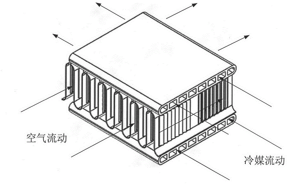
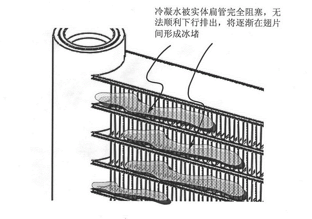
A parallel flow heat exchanger, tube-fin technology, applied in the direction of heat exchanger shells, tubular elements, heat exchange equipment, etc., can solve the problem that condensate water is difficult to discharge downwards, and no corresponding problems are proposed, so as to achieve smooth discharge and easy industrialization. The effect of chemical production and high heat exchange efficiency
- Summary
- Abstract
- Description
- Claims
- Application Information
AI Technical Summary
Problems solved by technology
Method used
Image

Examples
Embodiment Construction
[0029] In order to better illustrate the features of the present invention, the embodiments of the present invention will be described in detail below in conjunction with the accompanying drawings. This embodiment is carried out on the premise of the technical solution of the present invention, and the detailed implementation and specific damage process are given, but the protection scope of the present invention is not limited to the following embodiments.
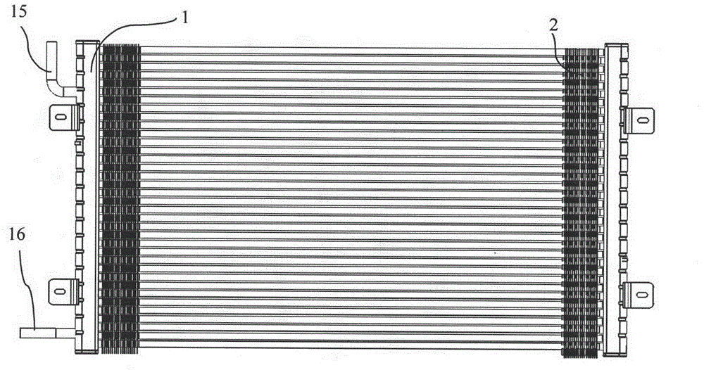
[0030] Such as Figure 3 ~ Figure 5 As shown, the tube-fin parallel flow heat exchanger of this embodiment includes a header 1, fins 2, and refrigerant tubes 3. The header 1 is provided with an end cover 13 and a baffle 14, and the refrigerant flows from the refrigerant inlet and outlet pipes. 15 enters the header 1, and the baffle plate 14 forces the refrigerant to flow in groups in the heat exchanger to form a group flow circuit 5, fully exchanging heat, and then flows out through the refrigerant inlet and outlet pipes ...
PUM
 Abstract
Description
Claims
Application Information