
Method and system for measuring half-wave voltage of electro-optical modulator

An electro-optical modulator and half-wave voltage technology, which is applied in the direction of measuring electrical variables, measuring current/voltage, measuring devices, etc., can solve problems such as errors, and achieve the effects of improving accuracy, facilitating control and locking

Active Publication Date: 2012-11-28
HUAZHONG UNIV OF SCI & TECH
View PDF5 Cites 19 Cited by
  • Summary
  • Abstract
  • Description
  • Claims
  • Application Information

AI Technical Summary

Problems solved by technology

[0009] The above two methods are only roughly observing the output optical signal of the electro-optic modulator, rather than measuring the half-wave voltage of the electro-optic modulator with precise mathematical expressions, so the traditional method of measuring the half-wave voltage is just a simple, Rough method, there is a large error

Method used


Image

  • Method and system for measuring half-wave voltage of electro-optical modulator
  • Method and system for measuring half-wave voltage of electro-optical modulator
  • Method and system for measuring half-wave voltage of electro-optical modulator

Examples


Embodiment 1

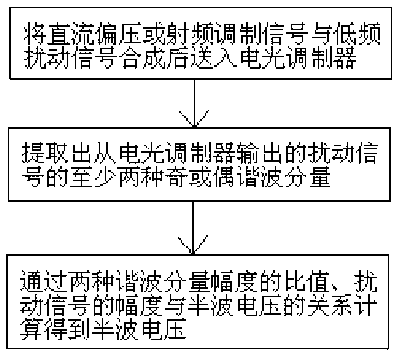
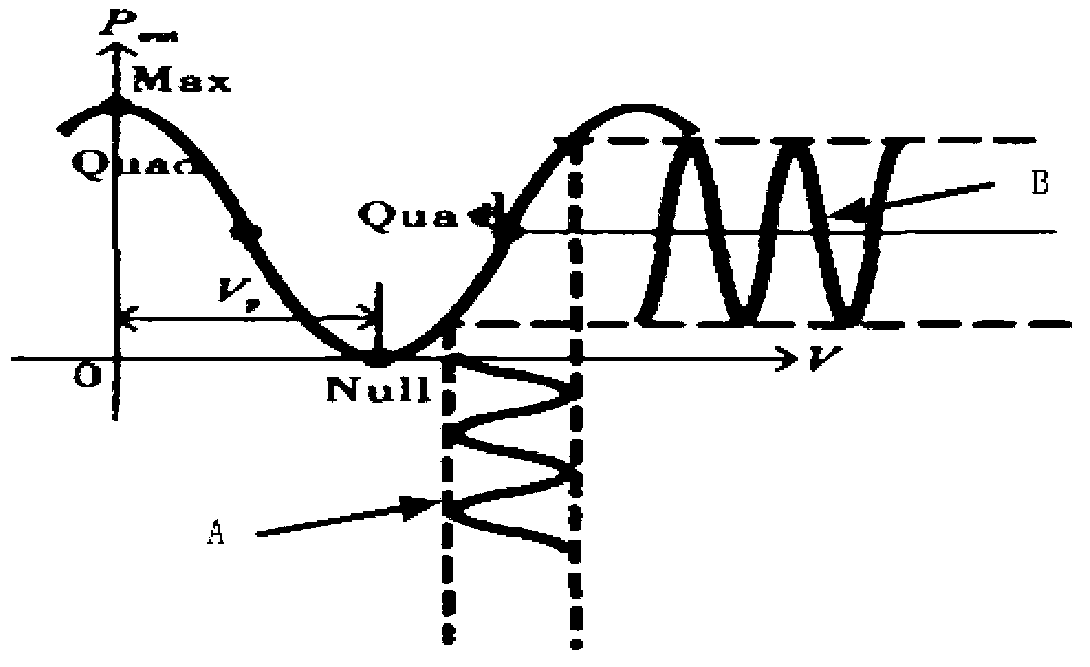
[0050] The DC half-wave voltage of the electro-optic modulator is measured by the method for measuring the half-wave voltage of the electro-optic modulator provided by the present invention. First, the DC bias voltage and the low-frequency disturbance signal are synthesized by the bias device and then sent to the DC bias of the electro-optic modulator. Voltage input; determine the transfer function of the electro-optic modulator, by image 3 It can be seen that the transfer function of the electro-optic modulator is as follows:

[0051] P out = 1 2 P in T d [ 1 + cos ( φ DC + φ RF ) ] - - - ( 1 ...

Embodiment 2

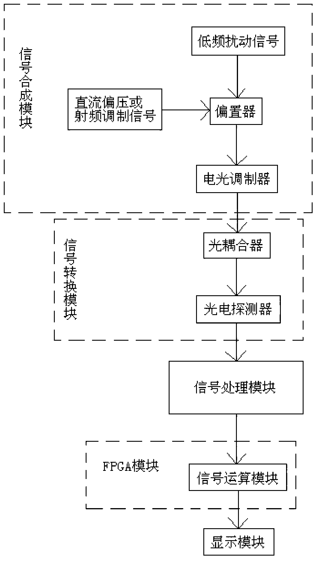
[0079] The DC half-wave voltage of the electro-optic modulator is measured by the measurement system of the half-wave voltage of the electro-optic modulator provided by the present invention. First, in the signal synthesis module, the DC bias voltage and the low-frequency disturbance signal are synthesized by the bias device and then sent to the electro-optic The DC bias input terminal of the modulator; the optical signal output by the electro-optic modulator passes through the optical coupler through the signal conversion module, and 10% of the optical signal enters the photodetector, and the photodetector converts part of the optical signal into an electrical signal ; Then the electrical signal is amplified by the signal processing module and converted by analog to digital, and the converted electrical signal is input into the FPGA module; the signal operation module is used to convert at least the low frequency disturbance signal in the FPGA module through fast Fourier transf...


PUM


Abstract

The invention relates to the technical field of optical fiber communication external modulation and discloses a method and system for measuring a half-wave voltage of an electro-optical modulator. According to the invention, not only influence from joggling of a power of lights output by a laser to a transmission curve of the electro-optical modulator and the half-wave voltage measurement can be removed and the measured half-wave voltage value is enabled to be more accurate, but the fast measurement is also realized. According to the method and system for measuring the half-wave voltage of the electro-optical modulator, disclosed by the invention, DC (Direct Current) half-wave voltage of the electro-optical modulator not only can be measured, but the radio frequency half-wave voltage also can be measured.

Description

technical field [0001] The invention relates to the technical field of optical fiber communication external modulation, and is mainly applicable to a half-wave voltage measurement method and a measurement system of an electro-optical modulator. Background technique [0002] In order to meet people's increasing information demand, the transmission rate of optical fiber communication system is increasing day by day. The future optical communication network will develop towards an optical fiber communication network with ultra-high speed, ultra-large capacity, ultra-long distance, and ultra-high spectral efficiency. To realize high-speed optical communication, the transmitter is the key. The high-speed optical signal transmitter is mainly composed of a laser that generates an optical carrier, a modulation electrical signal generating device, and a high-speed electro-optical modulator that modulates the optical carrier. Compared with other types of external modulators, lithium...

Claims


Application Information

Patent Timeline
Patent Type & Authority Applications(China)
IPC IPC(8): G01R19/00
Inventor 付松年冯振华唐明沈平刘德明
Owner HUAZHONG UNIV OF SCI & TECH
Learn More