Liquid crystal display (LCD) device

A technology of liquid crystal display device and liquid crystal display panel, which is applied to lighting devices, components of lighting devices, cooling/heating devices of lighting devices, etc., can solve the problems of difficult disassembly and assembly, disadvantageous operation efficiency, etc., and save operation time. , the effect of simple assembly or disassembly

Active Publication Date: 2012-11-28
TCL CHINA STAR OPTOELECTRONICS TECH CO LTD
View PDF4 Cites 17 Cited by
  • Summary
  • Abstract
  • Description
  • Claims
  • Application Information

AI Technical Summary

Problems solved by technology

The light strip 104 of the backlight module 100 is generally attached to the backplane 102 with heat dissipation glue 109 or locked with screws (not

Method used


Image

  • Liquid crystal display (LCD) device
  • Liquid crystal display (LCD) device
  • Liquid crystal display (LCD) device

Examples


Example Embodiment

[0025] In order to further illustrate the technical means adopted by the present invention and its effects, the following describes in detail in conjunction with preferred embodiments of the present invention and accompanying drawings.

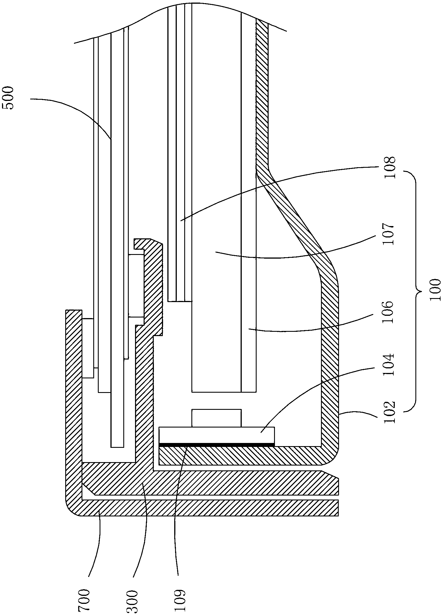
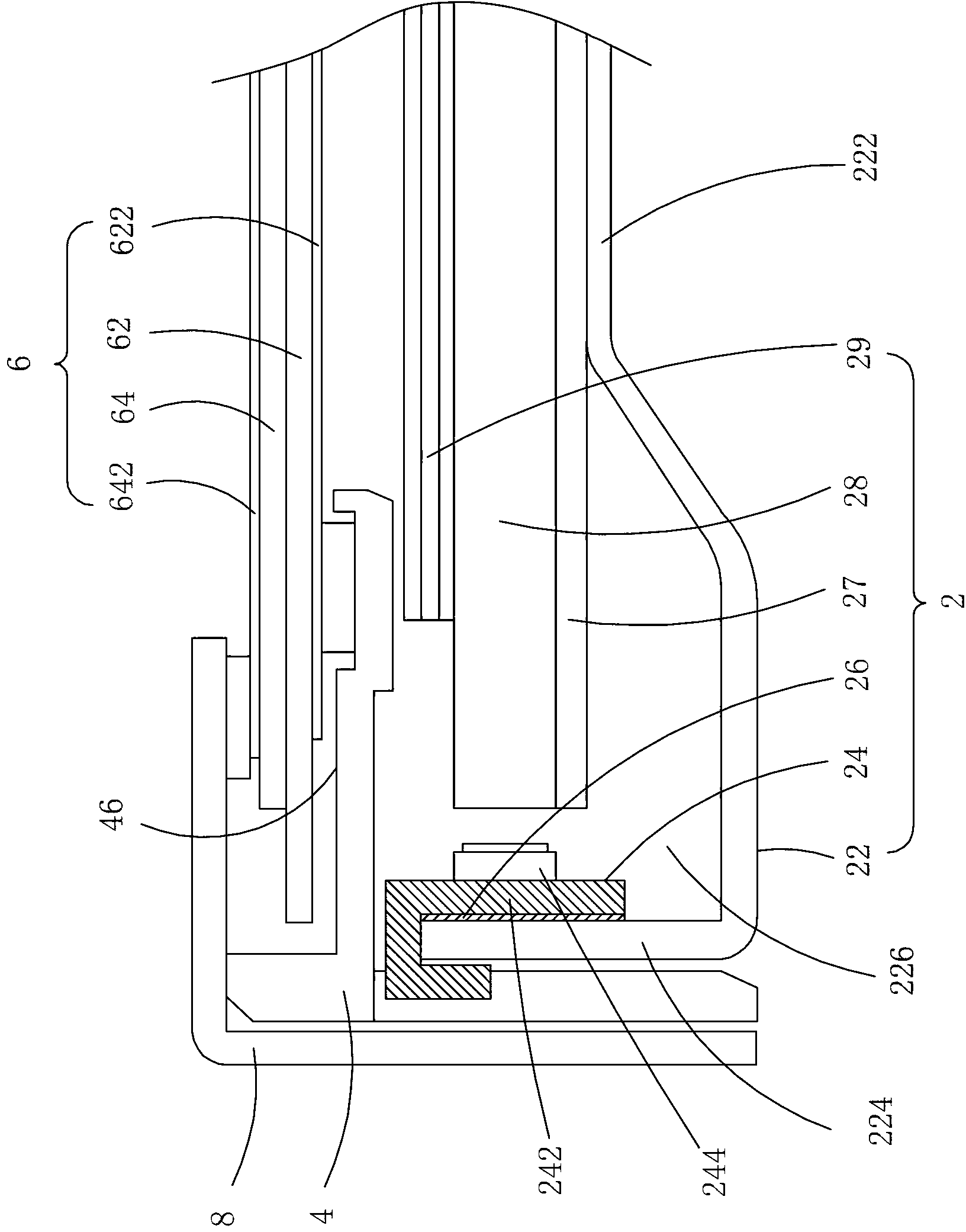
[0026] see Figure 2 to Figure 5 , the liquid crystal display device provided by the present invention includes: a backlight module 2, a plastic frame 4 disposed on the backlight module 2, a liquid crystal display panel 6 disposed on the plastic frame 4, and a front frame disposed on the liquid crystal display panel 6 8.

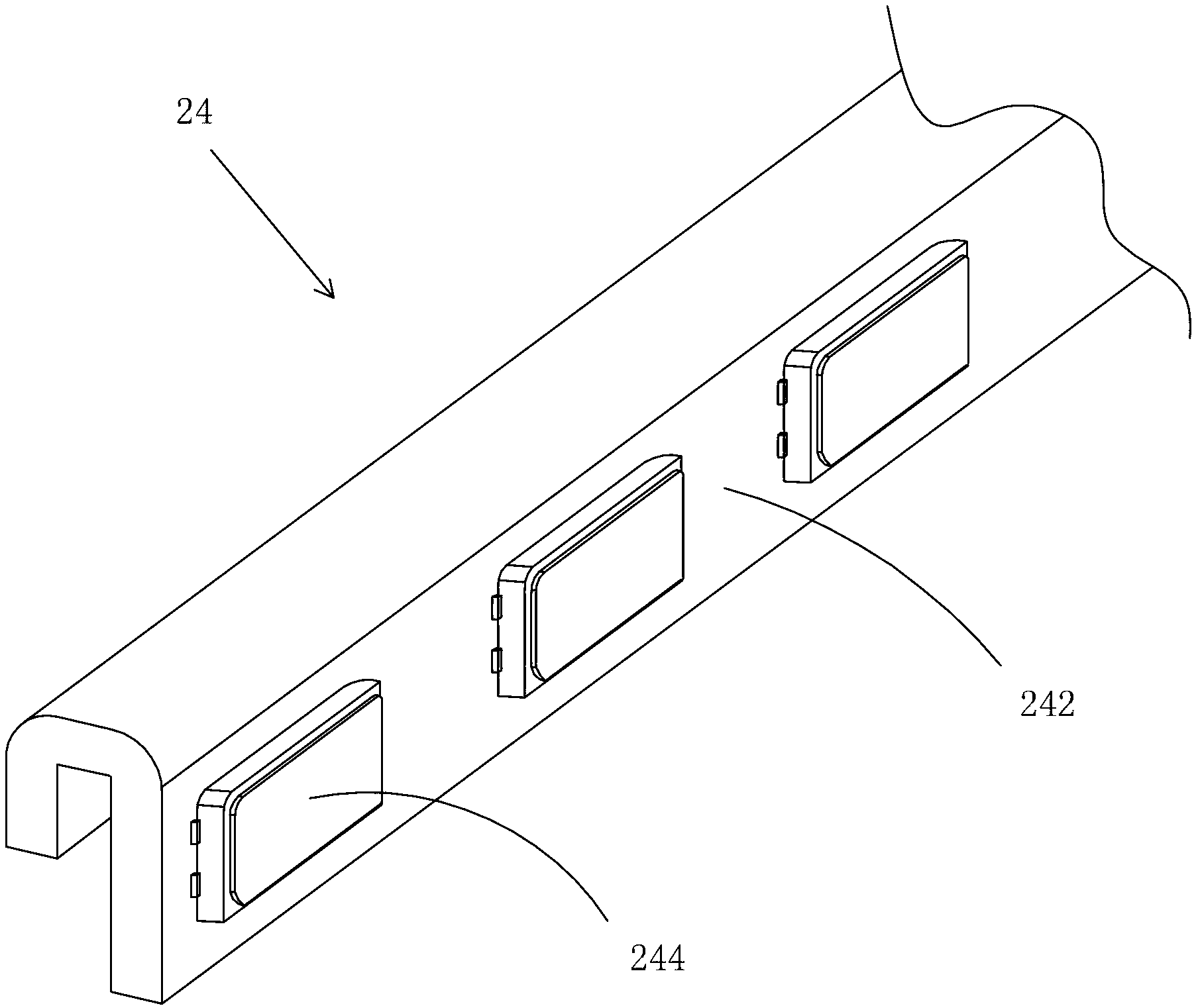
[0027] The backlight module 2 includes: a back plate 22, a light bar 24 installed on the back plate 22, a graphite sheet 26 arranged between the back plate 22 and the light bar 24, a reflector 27 arranged on the back plate 22, The light guide plate 28 disposed on the reflection plate 27 and the optical component 29 disposed on the light guide plate 28 . The light emitted by the light bar 24 enters the light guide plate 28 ...


PUM


Abstract

The invention provides a liquid crystal display (LCD) device. The device comprises a backlight module, a gel frame, an LCD panel and a front frame, wherein the gel frame is arranged on the backlight module; the LCD panel is arranged on the gel frame; the front frame is arranged on the LCD panel; the backlight module comprises a back board, a lightbar and a graphite sheet; the lightbar is installed on the back board; the graphite sheet is arranged between the back board and the lightbar; the lightbar comprises an inverted U-shaped metal base printed circuit board (PCB) and a plurality of LED (light emitting diode) lamps installed on and electrically connected with the metal base PCB; and the metal base PCB is clamped on the back board and then the lightbar is installed on the back board. The LCD device has the following beneficial effects: the lightbar is clamped on the back board by the inverted U-shaped metal base PCB and the graphite sheet is arranged between the lightbar and the back board to conduct heat to the back board to dissipate heat, the difficulty in assembly or disassembly caused by adopting the method that the lightbar is pasted by heat dissipation gel or locked by a screw so as to be fixed is avoided, a simpler assembly or disassembly method is provided and the operation time is saved.

Description


Claims


Application Information

Patent Timeline
Owner TCL CHINA STAR OPTOELECTRONICS TECH CO LTD
Why Eureka
Try Eureka