Human-machine interaction method and system based on binocular stereoscopic vision

A technology for binocular stereo vision and human-computer interaction, applied in the field of human-computer interaction methods and systems based on binocular stereo vision, can solve the problems of inconvenient installation and use, high hardware cost, inconvenient installation and use, etc. Simple and convenient installation and use, low cost, convenient and fast human-computer interaction

Active Publication Date: 2012-11-28
SHENZHEN INST OF ADVANCED TECH
View PDF7 Cites 93 Cited by
  • Summary
  • Abstract
  • Description
  • Claims
  • Application Information

AI Technical Summary

Problems solved by technology

Touch screen touch technology uses a screen made of special materials. Generally, the surface of the display is covered with a layer of transparent panel containing sensing wires, and the positioning of the finger contact position coordinates is realized through the sensing signal. The realization of this touch technology requires special materials. Screen, the hardware cost is high, and the screen needs to be fixed and cannot be moved
Visual touch technology uses a special infrared luminous pen to capture the movement trajectory of the infrared luminous pen with a camera, or install an infrared laser on the operation plane. When the finger touches the screen, an infrared spot is generated,

Method used


Image

  • Human-machine interaction method and system based on binocular stereoscopic vision
  • Human-machine interaction method and system based on binocular stereoscopic vision
  • Human-machine interaction method and system based on binocular stereoscopic vision

Examples


Embodiment 1

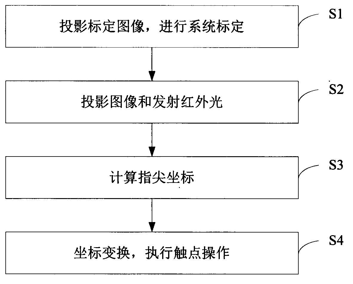
[0068] see figure 1 As shown, it is a flow chart of the human-computer interaction method based on binocular stereo vision in Embodiment 1 of the present invention. The method comprises the steps of:

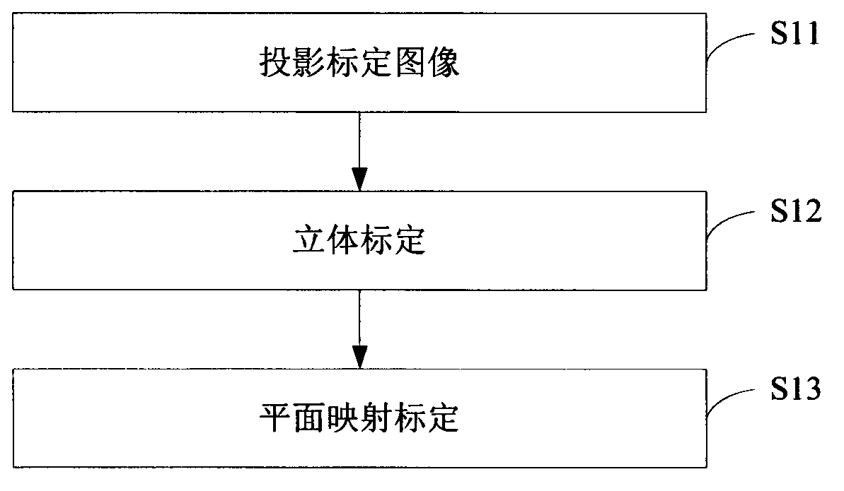
[0069] Step S1: Projecting a calibration image to perform system calibration.

[0070] In this step, the calibration image is projected onto the projection surface, and the calibration image on the projection surface is collected for system calibration. Using the method of this embodiment for human-computer interaction has no special requirements on the material of the projection surface, and various ordinary desktops and walls can be used as the projection surface. The calibration image can be projected by a projector, and the calibration image can be a checkerboard image. The final result of system calibration is a stereo calibration matrix that can calculate three-dimensional coordinates and a projection transformation matrix that can convert fingertip coordinates (ie, the...

Embodiment 2

[0138] The difference between this embodiment and Embodiment 1 is that in this embodiment, after calculating the three-dimensional coordinates of the fingertip, before converting the coordinates of the fingertip into screen coordinates, it first judges whether the fingertip is located in the preset projection plane. When it is within the preset projection plane, it is considered that the touch command is issued by the human hand. At this time, the fingertip coordinates are converted into screen coordinates and mouse motion information through the projection transformation matrix H. see Figure 8 As shown, it is a flow chart of the human-computer interaction method based on binocular stereo vision in Embodiment 2 of the present invention. For the convenience of description, only the steps starting from acquiring frame images are listed in the figure, and the steps before that are similar to those in Embodiment 1, and will not be described in detail here. The method mainly incl...

Embodiment 3

[0154] see Figure 9 As shown, it is a flow chart of the human-computer interaction system based on binocular stereo vision in Embodiment 3 of the present invention. The system includes electronic equipment, a projection device, an image acquisition device, an infrared light source and a projection surface. In this embodiment, the electronic equipment adopts a computer 1. The projection device adopts a micro-projector 2 , the image acquisition device adopts two cameras 3 , the infrared light source adopts two LED infrared lamps 4 , and the projection surface 5 is generated on an ordinary desktop 6 . The projection mode is vertical projection, and the micro-projector 2 , two cameras 3 and two LED infrared lamps 4 are vertically installed on the top of the projection surface 5 . Computer 1 is connected with micro-projector 2 and two video cameras 3 respectively; Two video cameras 3 are common video cameras and get final product, but all need band infrared filter (not shown in th...


PUM


Abstract

The invention relates to the technical field of human-machine interaction and provides a human-machine interaction method and a human-machine interaction system based on binocular stereoscopic vision. The human-machine interaction method comprises the following steps: projecting a screen calibration image to a projection plane and acquiring the calibration image on the projection surface for system calibration; projecting an image and transmitting infrared light to the projection plane, wherein the infrared light forms a human hand outline infrared spot after meeting a human hand; acquiring an image with the human hand outline infrared spot on the projection plane and calculating a fingertip coordinate of the human hand according to the system calibration; and converting the fingertip coordinate into a screen coordinate according to the system calibration and executing the operation of a contact corresponding to the screen coordinate. According to the invention, the position and the coordinate of the fingertip are obtained by the system calibration and infrared detection; a user can carry out human-machine interaction more conveniently and quickly on the basis of touch operation of the finger on a general projection plane; no special panels and auxiliary positioning devices are needed on the projection plane; and the human-machine interaction device is simple in and convenient for mounting and using and lower in cost.

Description

technical field [0001] The invention relates to the technical field of human-computer interaction, in particular to a method and system for human-computer interaction based on binocular stereo vision. Background technique [0002] Touch screens have been widely used, including smart phones, video conferencing, interactive electronic whiteboards, and product interactive advertising displays. In principle, touch screen technology can be roughly divided into two types: touch screen touch technology and visual touch technology. Touch screen touch technology uses a screen made of special materials. Generally, the surface of the display is covered with a layer of transparent panel containing sensing wires, and the positioning of the finger contact position coordinates is realized through the sensing signal. The realization of this touch technology requires special materials. The screen, the hardware cost is relatively high, and the screen needs to be fixed and cannot be moved. V...

Claims


Application Information

Patent Timeline
IPC IPC(8): G06F3/042
Inventor 宋展郗瑶颖马天驰刘晶
Owner SHENZHEN INST OF ADVANCED TECH
Why Eureka
Try Eureka