Environmental energy conversion device

A technology of energy conversion and environment, applied in measuring devices, using electrical devices, measuring heat, etc., can solve problems such as discontinuous electrical output, large volume and weight, and disorder.

Inactive Publication Date: 2012-11-28
NANJING UNIV OF AERONAUTICS & ASTRONAUTICS
View PDF4 Cites 15 Cited by
  • Summary
  • Abstract
  • Description
  • Claims
  • Application Information

AI Technical Summary

Problems solved by technology

However, lithium batteries and supercapacitors need to be charged before they can be used, and in order to increase energy density, large volume and weight are required
Solar cells need light to be used. Fuel cells consume fuel and cause great harm to the environment. Zinc oxide nanogenerators produce discontinuous electrical output, and capacitors are needed to store the generated electricity, which also consumes Mechanical energy
However, there is another form of energy, the energy of thermal motion of molecules, atoms, ions, and particles. For example, the thermal motion speed of gas molecules is as high as 1000 m / s, and the energy of thermal motion of ions in aqueous solution at room temperature is as high as 300 m / s. Because this movement is chaotic, so far there is no report of converting the energy of this thermal movement into electrical energy.

Method used


Image

  • Environmental energy conversion device
  • Environmental energy conversion device
  • Environmental energy conversion device

Examples


Embodiment 1

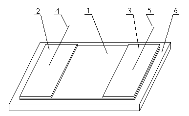
[0053] Such as figure 1 As shown, the environmental energy conversion device includes an energy conversion unit. The energy conversion unit includes an intermediate 1 , a positive electrode 2 and a negative electrode 3 . The intermediate 1 is connected to the positive electrode 2 and the negative electrode 3 , and is sandwiched between the positive electrode 2 and the negative electrode 3 . The intermediate body 1, the positive electrode 2, and the negative electrode 3 are installed on the substrate 6, and the positive electrode 2 and the negative electrode 3 are placed in parallel with a certain distance between them. The intermediate body sandwiched in the middle includes a contact surface with the outside world. For contact with intermediate media. The positive pole 2 is connected with a positive pole lead 4 , and the negative pole 3 is connected with a negative pole lead 5 . In order to avoid contact between the positive electrode 2 and the negative electrode 3 and the ...

Embodiment 2

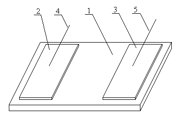
[0055] Referring to Example 1, different from Example 1, the semiconductor of the intermediate 1 of the energy conversion unit is a bulk material, thus the substrate 6 is missing, such as image 3 shown.

Embodiment 3

[0057] Referring to Example 2, the positive pole 2 and the negative pole 3 of the energy conversion unit adopt an asymmetric layout, such as Figure 4 As shown, the positive electrode 2 and the negative electrode 3 include a cross structure. Wherein, the contact area between the positive electrode 2 and the intermediate body 1 is smaller than the contact area between the negative electrode 3 and the intermediate body 1 .


PUM

PropertyMeasurementUnit
internal resistanceaaaaaaaaaa
thicknessaaaaaaaaaa

Abstract

The invention discloses an environmental energy conversion device which comprises an energy conversion unit, wherein the energy conversion unit comprises a positive pole, a negative pole and an intermediate; the intermediate is made of a semiconductor and is clamped between the positive pole and the negative pole, and two sides of the intermediate are respectively contacted with the positive pole and the negative pole; and the positive pole and the negative pole have asymmetry. The asymmetry of the positive pole and the negative pole refers to that the materials of the positive and negative poles have different work functions or different surface modification or different geometric structures; and the energy conversion unit can be connected in parallel and in series to form a whole environmental energy conversion device. The surface effect of the semiconductor is utilized, so that the environmental heat energy is continuously converted into electric energy in an environment, such as gas, liquid, gel or plasma, contacted with the semiconductor, particularly in solution, and a cooling effect is achieved. The environmental energy conversion device can be used for power generation and refrigeration, provides energy and refrigeration for various building constructions, transport equipment or electronic equipment, and can be used for concentration, temperature and flow velocity detection devices.

Description

technical field [0001] The invention relates to environmental energy conversion equipment of a new principle. Background technique [0002] Energy conversion and storage technologies include conversion of solar, thermal, vibrational, chemical and wind energy into electricity. Among these numerous energy conversion technologies, lithium batteries, supercapacitors, solar cells, fuel cells, and ZnO nanogenerators have received the most attention. However, lithium batteries and supercapacitors need to be charged before they can be used, and in order to increase energy density, they need a large volume and weight. Solar cells need light to be used. Fuel cells consume fuel and cause great harm to the environment. Zinc oxide nanogenerators produce discontinuous electrical output, and capacitors are needed to store the generated electricity, which also consumes Mechanical energy. However, there is another form of energy, the energy of thermal motion of molecules, atoms, ions, and...

Claims


Application Information

Patent Timeline
Patent Type & Authority Applications(China)
IPC IPC(8): H01L37/02H01L51/00H02N11/00F25B23/00G01K7/00G01N27/26G01P5/08
Inventor 台国安许子寒
Owner NANJING UNIV OF AERONAUTICS & ASTRONAUTICS
Why Eureka
Try Eureka