
Device for fuel cell electric pile assembly

A fuel cell stack and guide rod technology, which is applied to fuel cell grouping, fuel cells, fuel cell components, etc., can solve the problems of increasing the difficulty and cost of bipolar plate and MEA processing, sealing problems, etc. The effect of easy technology, uniform force and simple structure

Active Publication Date: 2012-11-28
武汉理工氢电科技有限公司
View PDF11 Cites 18 Cited by
  • Summary
  • Abstract
  • Description
  • Claims
  • Application Information

AI Technical Summary

Problems solved by technology

This not only increases the processing difficulty and cost of the bipolar plate and MEA, but also may cause sealing problems

Method used


Image

  • Device for fuel cell electric pile assembly
  • Device for fuel cell electric pile assembly
  • Device for fuel cell electric pile assembly

Examples


Embodiment 1

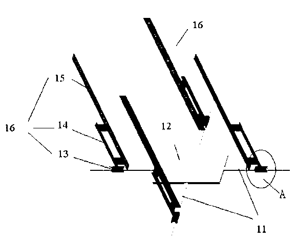
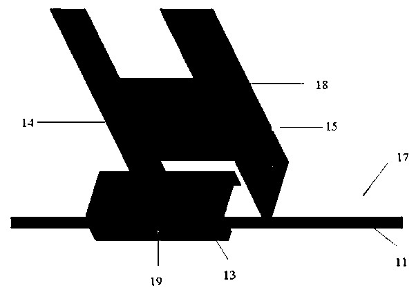
[0029] Such as Figure 2-3 Shown is the fuel cell stack assembly device of the present invention. Four guide rods 11 are arranged on the central axis of the chassis seat 12, and the thickness of the chassis seat 12 and the guide rods 11 are equal and the upper and lower surfaces are horizontal. The upper surface of the guide rod 11 is marked with a guide rod size scale 17 in millimeters or inches. A slider 13 is provided on the guide rod, and there is a threaded positioning hole 19 in the center of both sides of the slider. The slider 13 is fixedly connected with a supporting frame 14 and is perpendicular to each other. The slider can move along the axis direction on the guide rod. , and can be bolted through the threaded positioning hole 19. The vertical rod 15 is connected to the supporting fixture 14 by welding (or sticking), and the vertical rod 15 is perpendicular to the surface of the chassis base 12 . The slide block 13, the supporting fixture 14 and the vertical rod...

Embodiment 2

[0032] Such as Figure 4-5 Shown is another embodiment of the device for assembling fuel cell stacks of the present invention. In this embodiment, the vertical rod 15 is connected and fixed to the supporting and fixing frame 14 by bolts 20 to form a vertical rod assembly, and the vertical rod assembly is fixed by the supporting and fixing frame 14. On the slide block 13 , the slide block can move along the axial direction on the guide rod, and the slide block 13 can be fastened on the guide rod 11 with bolts through the threaded positioning hole 19 . Adjust the overlapping degree between the vertical rod assembly and the supporting fixture, so that the vertical rod 15 is perpendicular to the surface of the chassis base 12 .

[0033] A plurality of guide rods can increase the degree of alignment around the outer periphery of the battery, and setting the vertical rods and the support brackets to be movable and adjustable can reduce processing accuracy and thereby reduce processi...


PUM

PropertyMeasurementUnit
Thicknessaaaaaaaaaa
Lengthaaaaaaaaaa
Thicknessaaaaaaaaaa

Abstract

A device for fuel cell electric pile assembly comprises a chassis seat, guiding rods, vertical rods and support fixing frames; 2 or 4 guiding rods are symmetrically disposed at the side surface of the chassis seat along a central axis of the chassis seat; the guiding rods and the chassis seat form an integral structure; dimension scales are marked on the upper surface of each guiding rod; 2 or 4 support fixing frames and 2 or 4 vertical rods are provided; each one support fixing frame and each one vertical rod are assembled to form an integral body; a slide block is disposed at the bottom of each support fixing frame; a thread location hole is disposed on the slide block; the slide block can slide on the guiding rod along an axial direction; the slide block is fixed at a determined position on the guiding rod by the thread location hole; each vertical rod is vertical to the chassis seat; dimension scales are marked on the inner surface of each vertical rod. The device has a simple and flexible structure; fuel cell electric piles with different active areas and different specifications can be assembled through the position where the slide blocks are fixed on the guiding rods and the lengths of the vertical rods; the precision degree of the assembly and alignment of the fuel cell is improved, and the stability and security of the fuel cell are improved.

Description

technical field [0001] The invention belongs to the technical field of fuel cells, in particular to a fuel cell stack assembly device. Background technique [0002] Proton exchange membrane fuel cell (PEMFC) is a power generation device that directly utilizes hydrogen energy. PEMFC directly converts the chemical energy stored in hydrogen fuel and oxidant into electrical energy, and the energy conversion efficiency is high; the fuel cell is environmentally friendly and the only emission It is water. Therefore, fuel cell technology is considered to be the preferred clean and efficient power generation technology in the 21st century. [0003] When the proton exchange membrane fuel cell is working, under the action of the catalyst, the reaction that occurs is: [0004] [0005] The generated non-polluting water is directly discharged or recycled to humidify the gas, and the electrons generated by the electrode reaction reach the cathode through the external circuit, so that...

Claims


Application Information

Patent Timeline
IPC IPC(8): H01M8/24H01M8/02H01M8/2465
CPCY02E60/50
Inventor 潘牧叶东浩詹志刚涂正凯梁聪
Owner 武汉理工氢电科技有限公司
Learn More