Radiation unit and corresponding antenna array

A radiation unit and antenna array technology, which is applied in the field of antenna arrays, can solve problems such as the deterioration of high and low frequency patterns and the difficulty of suppressing the side lobes of radiation arrays, and achieve the effects of good product consistency, flexible manufacturing methods, and compact structure

Active Publication Date: 2012-11-28
TONGYU COMM INC
View PDF6 Cites 13 Cited by
  • Summary
  • Abstract
  • Description
  • Claims
  • Application Information

AI Technical Summary

Problems solved by technology

This design greatly reduces the width of the entire antenna in terms of arrangement, but at the same time there are the following problems: A. The distance between the high and low frequency oscillators is relatively close, and the two form a radiation boundary with each other, which c

Method used


Image

  • Radiation unit and corresponding antenna array
  • Radiation unit and corresponding antenna array
  • Radiation unit and corresponding antenna array

Examples


Embodiment approach 1

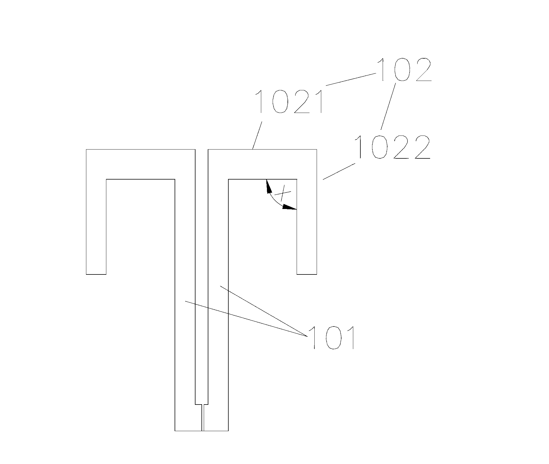
[0038] Embodiment 1, the low-frequency radiating unit A includes two sets of orthogonal linear half-wave oscillators 102 and a feed support device. The feed support device is a balanced balun 101, which includes two sets of metal plates that are parallel to each other and short-circuited at the bottom. Cylinder, the height of which is a quarter of the operating wavelength. The half-wave vibrator 102 includes a vibrator arm 1021 connected to the feed support device, and the free end of the vibrator arm is bent downward at an angle of 90 degrees to form a space loading section 102 .

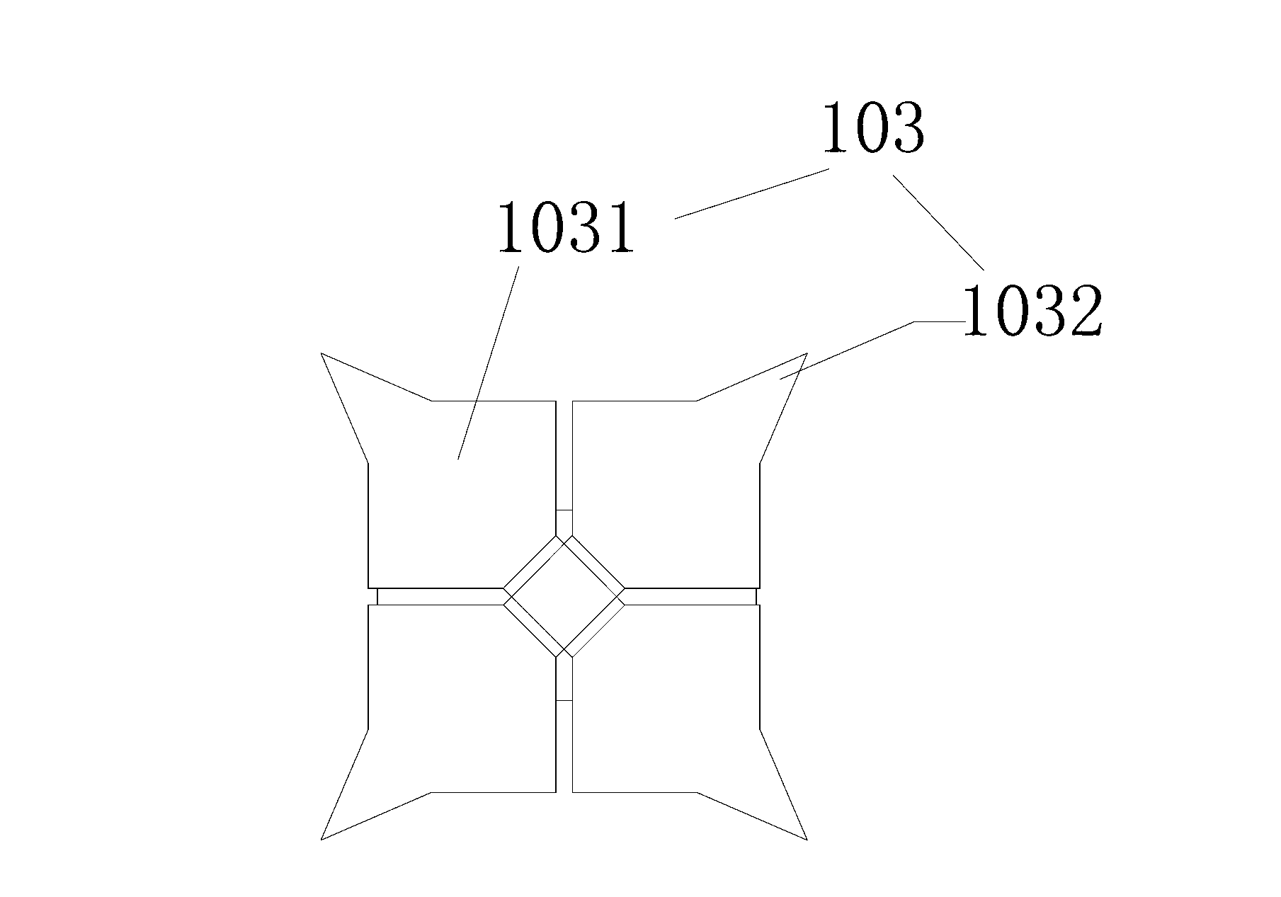
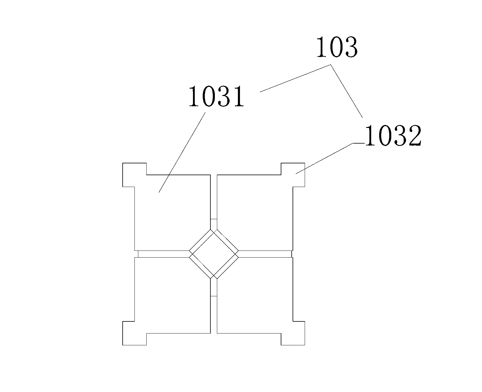
[0039] The high-frequency radiation unit B includes two sets of orthogonal planar half-wave oscillators 103 and a feed support device, the feed support device is a balanced balun 101, which includes two sets of metal cylinders parallel to each other and short-circuited at the bottom, Its height is a quarter of the operating wavelength. The vibrator arms 1031 of the planar half-wave vibrator are sq...

Embodiment approach 2

[0040] Embodiment 2: The low-frequency radiating unit A includes two sets of orthogonal linear half-wave oscillators 102 and a feeding support device. The feeding support device is a balanced balun 101, which includes two sets of metal plates that are parallel to each other and short-circuited at the bottom. Cylinder, the height of which is a quarter of the operating wavelength. The half-wave vibrator 102 includes a vibrator arm 1021 connected to the feed support device, and the free end of the vibrator arm is bent downward at an angle of 30 degrees to form a space loading section 1022 .

[0041]The high-frequency radiation unit B includes two sets of orthogonal linear half-wave oscillators 103 and a feed support device, the feed support device is a balanced balun 101, which includes two sets of metal cylinders parallel to each other and short-circuited at the bottom, Its height is a quarter of the operating wavelength. The half-wave vibrator 103 includes a vibrator arm 1031 ...


PUM


Abstract

The invention discloses a radiation unit, comprising two groups of orthorhombic half-wave vibrators and a feed supporting device. The radiation unit is characterized in that each half-wave vibrator comprises a vibrator arm connected with the feed supporting device; the free end of the vibration arm is bent downwards to form a space loading section; and a downward bending angle range of the space loading section is from 30 degrees to 90 degrees. Meanwhile, the invention further provides an antenna array formed by the radiation unit. The antenna array comprises a reflection board and a plurality of radiation units, and is characterized in that the radiation unit comprises a high-frequency radiation unit and a low-frequency radiation unit; each radiation unit is arranged along the symmetrical central line of the reflection board; and the two high-frequency radiation units are arranged between the two adjacent two low-frequency radiation units. With the adoption of the radiation unit and the antenna array provided by the invention, not only can the aperture size of the radiation unit be effectively reduced, but also the electric properties of pilot frequency isolation degree, directional diagram radiation properties and the like of the antenna in the array can be realized.

Description

technical field [0001] The present invention relates to the communication field, in particular to a radiation unit and a corresponding antenna array Background technique [0002] With the rapid development of mobile communication technology, major mobile communication equipment manufacturers and operators, especially in some European countries, have increasingly strict requirements on the electrical performance index and antenna size of the antenna. Compared with the traditional single-frequency antenna, the dual-frequency antenna has the advantages of reducing the number of antennas, lowering the requirements on the site, and saving the investment in base station construction. It has high use value and performance advantages, so it is widely used. [0003] In the existing technical solution, the dual-frequency antenna can be realized by sharing the radiating unit, but in order to realize the independent antenna downtilt angle, it is usually required to use an independent fe...

Claims


Application Information

Patent Timeline
IPC IPC(8): H01Q1/36H01Q1/50H01Q21/30H01Q19/10
Inventor 洪何知吴中林石磊陈光叶海欧曹林利余夙琼
Owner TONGYU COMM INC
Why Eureka
Try Eureka