Internet of things system and acquisition and monitoring method for article information

An Internet of Things system and item information technology, which is applied in the field of Internet of Things system and item information acquisition and monitoring, can solve the problems of lack of middle layer, difficulty in building the Internet of Things, singleness, etc.

Active Publication Date: 2012-11-28
SHANGHAI GOKEI INFORMATION TECH
4 Cites 49 Cited by

AI-Extracted Technical Summary

Problems solved by technology

Compared with other standards, its biggest flaw is the lack of an intermediate layer. Generally, it only de...

Method used

As shown in Figure 3, the first and second mobile terminals 11 and 12 are all made up of 5 parts, wherein the first mobile terminal 11 skips the service layer and directly communicates with the subnetwork gateway layer 30, which has a request gateway service The gateway service request module 11E and the push response module 11D that receives various push services from the gateway. The second mobile terminal 12 communicates with the service layer, and has a service layer service request module 12E for requesting security service functions and a push response module 12D for receiving various push services from the service layer. The first and second mobile terminals 11, 12 respectively include an embedded database 11B, 12B inside, and the embedded database 11B, 12B can store intermediate data or temporary data; system function modules 11C, 12C include respective basic configuration information , business logic processing and scheduling of other modules, the system function modules of the first mobile terminal 11 mainly process instruction data, and the system function modules of the second mobile terminal 12 mainly process business data; the graphical interfaces 11A and 12A are multiple Each platform can be customized, for example, Apple's IOS platform, android platform, Windows platform and Linux platform, etc. The graphical development of these platforms is simple and fast, and the display effect is realistic. It can load intuitive spatial data display scenes, and various graphic display objects and sensors, combined with time and specific application business logic, it can adapt to various Internet of Things applications.
Preferably, the RFID read-write module 51A is also provided with a fluid sensor to monitor whether the air flow velocity in the cabinet reaches a predetermined standard, preventing the overall temperature from rising in the cabinet caused by air stagnation;
[0135] Both the subnet gateway layer and the access layer belong to middleware. Middleware is the nervous system of the Internet of Things, a general architecture for managing data. This distributed structure can simplify the management of the Internet of Things and improve operational efficiency. Middleware is software used to process and process all information and event flows from underlying hardware such as readers, sensors, and smart devices. It is the link between the underlying hardware and the background management system. It needs to filter, group and count tag data and sensor data, and finally form instruction data and send it to the service layer to reduce the amount of data in the network system and prevent wrong reading, missed reading and over-reading information. "Edge middleware" is a middleware that is directly connected to the underlying hardware to collect real-time data. "Internal middleware" is mainly responsible for transferring the data collected by "edge middleware" to the background management system through a multi-level network.
[0189] A in the figure is a schematic diagram of the copper cable RFID electronic distribution frame structure. The entire distribution frame includes three parts, one part is a common network distribution frame 131_1, and the other part is a passive RFID ...

Abstract

The invention discloses an Internet of things system and an acquisition and monitoring method for article information. The system comprises perception guiding equipment, a sub-network gateway, service layer equipment and view layer equipment, wherein the perception guiding layer equipment is used for controlling a monitored object of the Internet of things according to an instruction, acquiring data information and uploading the data information to the sub-network gateway; the sub-network gateway is used for processing the instruction, and performing the interaction of the data information interaction through a network and the service layer equipment; the service layer equipment is used for processing the instruction and the data information according to the service type of Internet of things application and preset configuration, and transmitting the processed data information to the view layer equipment; and the view layer equipment is used for requesting data to the service layer equipment and receiving the data of a service layer for display. By the system and the method, network Internet of things application and the Internet of things application of other industries can be extended.

Application Domain

TransmissionSpecial data processing applications

Technology Topic

Service layerProcessing Instruction +4

Image

  • Internet of things system and acquisition and monitoring method for article information
  • Internet of things system and acquisition and monitoring method for article information
  • Internet of things system and acquisition and monitoring method for article information

Examples

  • Experimental program(1)

Example Embodiment

[0098] The technical solutions of the present invention will be further described below in conjunction with the drawings and specific implementations.
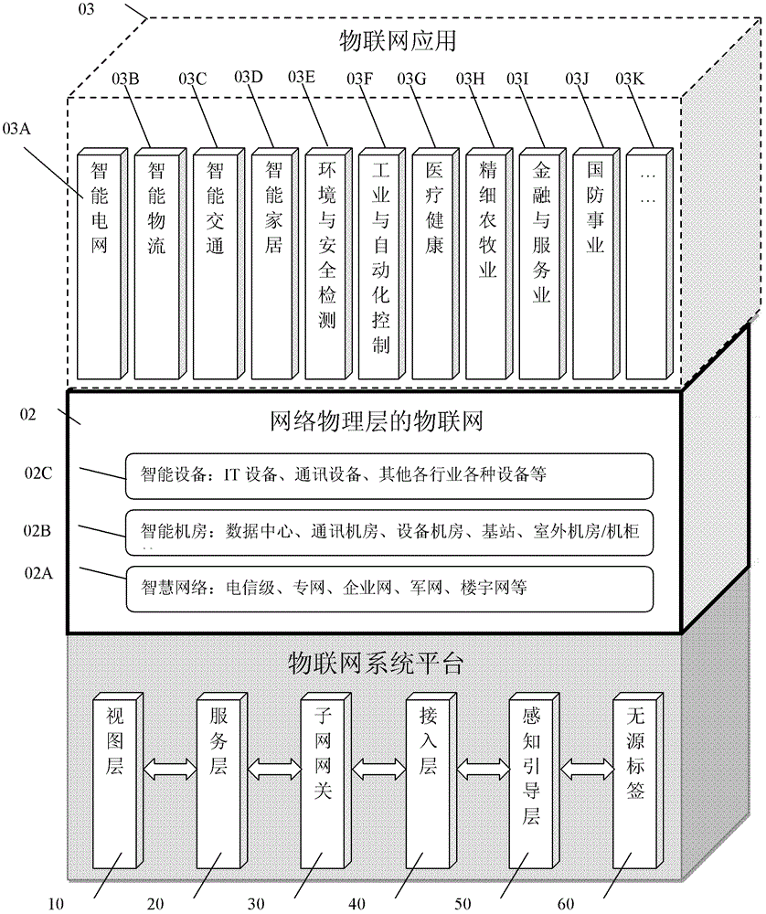
[0099] figure 1 It is a schematic diagram of the overall structure of the Internet of Things application system of the present invention. The Internet of Things application system of the present invention includes three parts, the Internet of Things system platform 01 and the Internet of Things 02 at the network physical layer, namely "Internet of Things" and Internet of Things Application 03.
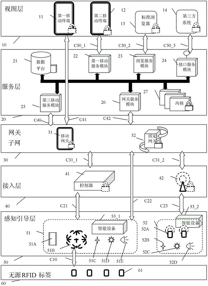
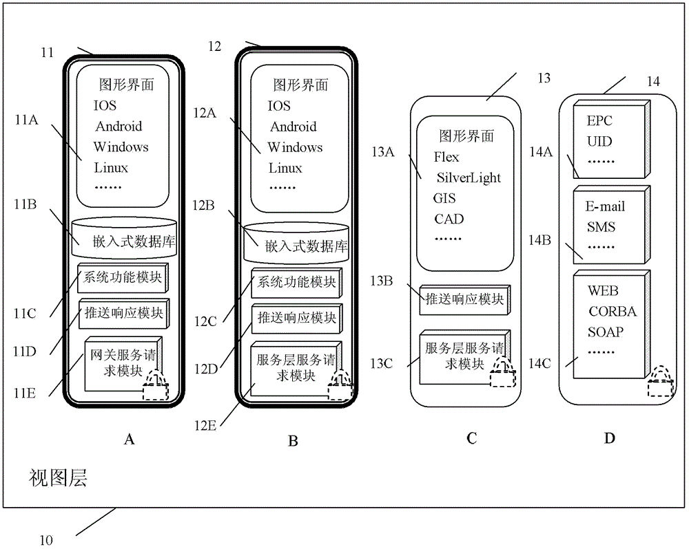
[0100] Among them, the IoT system platform is divided into six layers, namely, the view layer 10, the service layer 20, the subnet gateway layer 30, the access layer 40, the perception guidance layer 50 and the passive RFID electronic tag 60. A complete IoT system is basically composed of several or all of these six parts.
[0101] The Internet of Things at the network physical layer is a typical Internet of Things system built on this platform. This system performs unified real-time monitoring and management of all terminal equipment and physical links in IT and communication networks. The Internet of Things system is divided into three levels in terms of functions, namely Smart Network 02A, which performs real-time monitoring, positioning and intelligent management of the physical links of the carrier-level network, private network, enterprise network, military network, and building network. ; Intelligent computer room 02B, real-time monitoring, positioning and intelligent management of the internal environment, equipment and itself of the data center (IDC), equipment room, communication room, base station, outdoor transfer box, outdoor cabinet, etc.; intelligent equipment 02C, in Real-time monitoring, positioning and intelligent management of IT equipment, communication equipment and various IoT equipment in various industries at any location.
[0102] Communication network and IT are the foundation of all Internet of Things, so it is very easy to expand other Internet of Things applications on the basis of Internet of Things. Sensors, RFID read-write devices, active RFID tags, and industry smart devices in most industry IoT will be directly managed by the network as a terminal of the network. With the expansion of the business function modules of the service layer, it can realize the following: Smart grid 03A, smart transportation 03B, smart logistics 03C, smart home 03D, environment and safety detection 03E, industrial and automation control 03F, medical health 03G, fine agriculture and animal husbandry 03H, financial and service industry 03I, national defense and military 03J, and other applications 03K.
[0103] figure 2 It is a schematic diagram of the structure of the Internet of Things system platform of the present invention. Such as figure 2 As shown, the service layer 20 is the core of the entire platform, which includes a data platform 21 for providing data storage, a core 27 for core business logic processing, and a module for providing access services for peripheral devices (including the view layer The second mobile terminal 12 provides a mobile service module 22 for accessing services, a browsing service module 23 for providing access services for the browser 13 at the view layer, a third-party service module 24 for providing interface services for a third-party system at the view layer, and a mobile child The mobile service module 25 that provides services to the network gateway 31, and the gateway service module 26 that provides services to the fixed subnet gateway 32).
[0104] The service mode of the service layer 20 for each object in the view layer 10 is provided through the interfaces C50_1, C50_2, C50_3 of the local area network or the wide area network, and the service layer 20 generally does not manage the requested objects. The communication interface C42 between the service layer 20 and the fixed subnet gateway 32 and the communication interface C40 between the mobile subnet gateway 31 are generally performed through a wide area network, and necessary management of communication objects is performed.
[0105] The subnet gateway layer 30 is the central nerve of the entire platform. It generally includes a fixed subnet gateway and a mobile subnet gateway. The fixed subnet gateway 32 exists in each local area network, and each subnet segment requires a fixed subnet gateway 32. The subnet gateway layer 30 provides services to the service layer 20 through the wide area network/local area network interface C42/C40. It can also act as an agent of the service layer 20 to directly provide data and security services from the service layer to the first mobile terminal 11 of the view layer 10, and the communication interface C41 between the two is generally a local area network. The most important function of the subnet gateway layer 30 is to perform data communication and ensure security for its lower devices, the controller 41 and the wireless gateway 42, and process their command data. The communication interfaces C31_1 and C31_2 between them are generally local area networks. The subnet gateway layer 30 can also directly communicate with the lower device of the perception and guidance layer-the communication interface C22 supporting the local area network and the passive RFID reading and writing device 51 or the smart device 53_1 that supports command control, process its command data, and control it through commands These devices. This layer also receives instruction data from the service layer 20 through the WAN/LAN C42/C40, and controls the lower-level equipment according to the instructions.
[0106] The access layer 40 is a nerve in an independent subnet and a branch nerve of the entire system. The access layer 40 includes a controller 41 that connects to passive RFID readers and smart devices through the interface C21, and controls these devices in real time; and connects to active RFID and wireless smart devices through the wireless communication interface C23, and performs The wireless gateway 42 for mutual data conversion.
[0107] The controller 41 of the access layer 40 can control the passive RFID reader 51 and the smart device 531 through a serial port, USB, or other wired interface C21. The wireless gateway 42 communicates with an active RFID tag 52 or a smart device 532 that supports wireless communication through, for example, ZigBee/Wi-Fi and other wireless communication interfaces C23 that support ad hoc networks.
[0108] The sensing and guiding layer 50 is mainly a passive RFID reader 51, an active RFID tag 52, and smart devices 53_1 and 53_2. The passive RFID reader 51 is composed of a reader module 51A, an antenna and an antenna array 51B, a sensor 51C, an indicator light 51D, and a sound device (buzzer or horn) 51E. The antenna or array antenna reads, writes and locates the passive RFID tag 61 through the radio frequency interface C10. The active RFID tag chip 52A can transmit data through Zigbee/Wi-Fi/other wireless networks that support ad hoc networks, and finally transmit the data to the wireless gateway. It is active, so it can integrate sensors 52B, indicator lights 52C, and sound Equipment (buzzer or horn) 52D. Smart devices 53_1, 53_2 mainly refer to various systems such as industrial systems, building control systems, home smart facilities, video surveillance systems, etc., with various interfaces such as USB, serial, or Ethernet, and wireless interfaces, and can be Devices that remotely send control instructions and obtain current real-time status and data through these interfaces, such as: smart air conditioners and smart UPSs in data centers, smart washing machines and smart rice cookers in smart homes, etc.
[0109] The types of communication interfaces between the above-mentioned layers are as follows:
[0110] Interfaces C10 and C23 are wireless interfaces, such as Wi-Fi/ZigBee/LF RFID/HF RFID/UHF RFID, etc.
[0111] The interface C21 is an interface between the underlying hardware of the wired connection.
[0112] The interfaces C22, C31_1, and C31_2 are LAN interfaces.
[0113] The interface C42 is an Internet or LAN interface.
[0114] Interfaces C40, C41, C50_1, C50_2, C50_3 are network connection interfaces, which can be wired or wireless local area networks or wide area networks. The form is indefinite, as long as there is a network connection.
[0115] The data transmitted by the communication interface between the above layers are as follows:
[0116] Interface C10 transfers the underlying hardware data.
[0117] Interface C21, C23 transfer instruction data or underlying hardware data
[0118] Interfaces C22, C31_2, C41, C42, C31_1, C40 transfer instruction data.
[0119] The interfaces C50_1, C50_2, C50_3 transfer service data.
[0120] The various layers of the Internet of Things system of the present invention will be further described below with reference to the accompanying drawings.
[0121] image 3 It is a schematic diagram of the view layer structure of the IoT system platform according to an embodiment of the present invention.
[0122] One of the characteristics of the Internet of Things system is: things, time and place. Based on the scene, the relationship between the scene and the object is structured, and the relationship between the object and time is expressed on this basis. The scene can be switched according to actual needs, and the objects and various sensor information can be loaded according to the scene, time and other conditions. Therefore, based on the intuitive graphical interface, adding different objects according to different applications can be applied to many application scenarios.
[0123] Such as image 3 As mentioned, the first and second mobile terminals 11 and 12 are composed of 5 parts. The first mobile terminal 11 skips the service layer and directly communicates with the subnet gateway layer 30, and it has a gateway service request module 11E that requests gateway services. And the push response module 11D that receives various push services from the gateway. The second mobile terminal 12 communicates with the service layer, and has a service layer service request module 12E that requests a security service function and a push response module 12D that receives various push services from the service layer. The first and second mobile terminals 11, 12 respectively include an embedded database 11B, 12B, the embedded database 11B, 12B can store intermediate data or temporary data; the system function modules 11C, 12C contain their basic configuration information , Business logic processing and scheduling of other modules, the system function module of the first mobile terminal 11 mainly deals with instruction data, and the system function module of the second mobile terminal 12 mainly deals with business data; the graphical interfaces 11A, 12A are multiple Each platform can be customized, for example, Apple's IOS platform, android platform, Windows platform and Linux platform. The graphical development of these platforms is simple and fast, and the display effect is realistic. It can load intuitive spatial data display scenarios, as well as various graphic display objects and sensors, combined with time and specific application business logic, and can be adapted to various IoT applications.
[0124] The browser 13 in the presentation layer also uses the most intuitive graphical operation interface 13A (it contains many graphical technologies, generally one or more of Flex, SilverLight, GIS, CAD and other graphical technologies, to the greatest extent The graphic effect of the display shows the application of the Internet of Things, which can be applied to many industries); the browser 13 communicates with the service layer 20, including a service layer service request module 13C that requests security services and a push response module 13B that receives various push services from the service layer .
[0125] The third-party system 14 is another view-layer device with display and interactive functions, and its interface with the service layer is generally divided into three categories.
[0126] One is an interface reserved for adapting to open-loop applications of the Internet of Things. The so-called open loop, like EPC and UID, the entire system is open, and there are unified open specifications for coding, architecture, information interaction, and reading and writing rules. Any system that follows the specifications can interact in real time. Closed loop means that you can define all the rules by yourself, as long as the internal system and the brother systems can interact in real time. In order to adapt to the open-loop standard, the present invention sets up a special open-loop interface 14A. In the open loop interface, a local EPCIS or UID information service can be set to be open to EPC and UID standards.
[0127] The second is compatibility with third-party systems. It is generally called the northbound interface of the system, which is convenient for third-party systems to call the services of this system. The northbound interface 14C of the present invention includes: WEB service, CORBA and SOAP.
[0128] The third is some standard message interface 14B, such as SMS, E-mail, etc. The recipients of these standard messages can be set in the system, and the system can send messages to the recipients when needed.
[0129] Figure 4 It is a schematic diagram of the service layer structure of the Internet of Things system platform according to an embodiment of the present invention.
[0130] Drawing lessons from SOA ideas, a service-based and scalable software architecture can be constructed. Classify the business into service components of different granularities. With the idea of ​​object-oriented and aspect programming, the whole system can expand various functions indefinitely (as long as the hardware permits, theoretically possible), load different functions according to user needs. To the user. Software servitization has become a trend, and the service layer is the result of seeking minimal servitization for the complex business, data and security processing requirements of the entire Internet of Things system.
[0131] The service layer 20 can provide different services for different external requests, and push information to the requester when necessary. The service layer 20 includes a second mobile service module 22 corresponding to an external service request of the second mobile terminal 12; a browsing service module 23 corresponding to an external service request of a standard browser 13; and a third-party system 14 corresponding to an external service request The third-party service module 24; the third mobile service module 25 corresponding to the mobile subnet gateway 31; the gateway service module 26 corresponding to the fixed subnet gateway 32.
[0132] The data platform 21 is one of the most important functional modules of the service layer. The data platform 21 includes a relational data processing module 21A, a spatial data processing module 21B, a vector data processing module 21C, and a file data processing module 21D. The relational data processing module 21A can abstract multiple relational databases, relational database 1, relational database 2, or more into persistent layer objects, and organize the persistent layer objects to provide external data services according to business logic requirements. The spatial data processing module 21B stores basic data in a spatial database, and the spatial engine is responsible for analyzing and processing different spatial objects, and expressing the relationship between them. The space service is based on the space engine, and different space data analysis objects and methods are established according to business logic requirements. There is still a large amount of vector data in the application of the Internet of Things, so this system designs a vector data processing module 21C, the vector database is responsible for storing the vector data, and the vector data engine constructs vector objects according to the data structure and expresses the relationship. Based on vector objects, vector services establish different vector data analysis objects and methods according to business logic requirements. In addition, there is a large amount of file information that needs to be processed in any system, so this system designs a file data processing module 21D, and establishes a special file service for file management rules for other parts of the system to call.
[0133] The core 27 includes a business function module 27D responsible for business logic processing, a security service module 27C, a networking service module 27E, a system service module 27B, a bus service module 27A, and a message service module 27F. The system service module 27B contains basic configuration information of the entire system, such as unit information, hardware configuration, personnel information, authority settings, module configuration, multi-language, and so on. The security service module 27C mainly includes the security of internal information, the security of data storage, the security of external services and data communication in the interface, and the security of the identity and authentication of hardware devices. One of the most complicated is the security of data in network communications. will be Picture 12 Details in the. The networking service module 27E is for networking the lower subnet gateway or the mobile terminal connected to the background service, and for real-time management of the subnet gateway 30. These devices may be accessed temporarily or permanently, that is, they may be directly accessed or indirectly accessed through gateways or firewalls. The system must be able to discover these devices in time when they are connected, know when they leave, and manage the necessary network identities. The business function module 27D is mainly to establish different functional module groups for different IoT applications, such as: smart grid, smart transportation, smart logistics, smart home, environment and safety detection, industrial and automation control, medical health, fine agriculture and animal husbandry , Financial and service industries, national defense and military, etc., can continue to expand. Different modules can be subdivided into more granular sub-function modules according to specific functions. Module 27D1 shows the specific functional module blocks that need to be added every time an IoT application is added, including: business data, business logic, graphical interface, underlying hardware information and control methods (this is the basis for hardware instruction generation and analysis). The main function of the bus service module 27A is to configure, call and coordinate the above service components. When a function module needs to perform a certain function or an external service needs to perform a certain function, other service components are bound to be involved. At this time, the bus service will coordinate these services and complete the work. The message service module 27F is used to process and encapsulate business data and instruction data of different applications before being transferred between the various layers of the system platform, and to analyze and process after the transfer.
[0134] Figure 5 It is a schematic diagram of the structure of a mobile subnet gateway of an Internet of Things system platform according to an embodiment of the present invention. Image 6 It is a schematic diagram of a fixed subnet gateway structure of an IoT system platform according to an embodiment of the present invention. Figure 7 It is an architecture diagram of the access layer of the IoT system platform according to an embodiment of the present invention.
[0135] Both the subnet gateway layer and the access layer belong to middleware. Middleware is the nervous system of the Internet of Things and a general data management architecture. This distributed structure can simplify the management of the Internet of Things and improve operational efficiency. Middleware is the software used to process and process all information and event streams from readers, sensors, smart devices and other underlying hardware. It is the link between the underlying hardware and the background management system. It needs to filter, group and count tag data and sensor data, and finally form instruction data and send it to the service layer to reduce the amount of data in the network system and prevent false reading, missed reading and multiple reading of information. "Edge middleware" is a middleware that is directly connected to the underlying hardware and collects real-time data. "Internal middleware" is mainly responsible for transmitting the data collected by the "edge middleware" to the back-end management system through a multi-level network.
[0136] The middleware can be either an independent software package or an embedded software package in form, or an independent hardware plus various embedded software packages. Most of them are pure software middleware, but the hardware of the embedded device is used as the ES layer middleware in the present invention. The hardware middle layer has its own advantages. In addition to the networking and computing functions of the software middleware, it also has a wealth of hardware interfaces, which can connect various readers, sensors, smart devices, and even other and Internet of Things Irrelevant equipment, and control these equipment from the hardware or physical communication. The release and networking of the hardware middle layer is also more convenient than software middleware. The disadvantage is that the production cost is high.
[0137] Figure 5 The illustrated mobile subnet gateway 31 is similar in function to the internal middleware described.
[0138] The mobile subnet gateway 31 includes an interface module 31A, which directly requests services from the service layer and accepts information pushed from the service layer. The core module 31B includes embedded data processing, instruction processing, system function realization, and graphical interface. The system function module is the core, including business logic processing, necessary system configuration, and coordination of other parts of work. The instruction processing module mainly encapsulates, analyzes, distributes and executes instruction data. Embedded data processing is mainly the storage, query and management of system data, intermediate data, and temporary data. The graphical interface displays the results graphically according to the system function needs, interacts with the user, and transmits the result to the system function. In order to have a better graphical effect, generally choose an operating system with a better graphical effect, such as: IOS, Android, Windows, Linux, etc. The network communication module 31C communicates with the different underlying hardware that is connected to the mobile subnet gateway through the local area network. On this platform, it is mainly a controller, a wireless gateway, a passive reader and a smart device.
[0139] Such as Image 6 As shown, the main function of the fixed subnet gateway 32 is similar to internal middleware, and is responsible for communicating with edge middleware, and divides the edge middleware/hardware middleware into different network segments. There is little or no communication between different network segments, which greatly reduces the complexity of the system and improves efficiency. The entire fixed subnet gateway 32 is divided into three layers, namely the interface layer 321, the core layer 322, and the network layer 323. The interface layer mainly provides a service interface to the first mobile terminal 11 through the first mobile service module 321A, and provides a service interface 321B to the service layer 20 through the service layer service module 26. Since all the networking of the subnet gateway and the service layer are managed by the networking service 27E of the service layer, the service layer gateway service module 26 can directly call the service layer service module 321B of the subnet gateway, and the service layer service module 321B also The gateway service module 26 can be called directly. The first mobile terminal 11 may directly request the first mobile service module 321A of the subnet gateway to provide services, and the first mobile service module 321A may also directly push information to the mobile terminal. The core layer 322 includes a data service module 322C, a security service module 322D, a network service module 322B, an instruction service module 322E, and a system service module 322A. Among them, the data service module 322C includes an embedded database component, which can process all system data, intermediate data and temporary data like relational data, and provide services for other service components. The security service module 322D provides mutual security authentication, encryption and decryption for the communication between the subnet gateway and the service layer, and provides security services for the external interface. The system service module 322A is the core of the subnet gateway for the realization of the basic functions of the entire system, the configuration of the system, and the scheduling between modules. It is responsible for all business logic processing and calls other different service components according to the business logic. The instruction service 322E analyzes, encapsulates, and distributes instruction data. Since business data is processed in the service layer, the business data in the subnet gateway is used as instruction data parameters to interact between the service layer and the subnet gateway. The network communication module 322B is the networking management for those devices that access to the subnet gateway through the local area network and accept the subnet gateway management and security certification, and the specific networking methods for different underlying hardware are slightly different, and these differences are all in advance. There are corresponding settings in the hardware information and control mode in the business function modules of the service layer. On this platform, it is mainly controllers, wireless gateways, passive readers and smart devices. This information is used at the beginning of the subnet gateway. Is loaded in. The network layer 323 establishes and manages different underlying TCP/IP network connections according to the configuration of the network service module 322B of the core layer 322, and filters and analyzes the transferred data. These analysis and filtering methods are also pre-defined in the hardware information and control methods in the business function modules of the service layer, and these information are loaded at the beginning of the subnet gateway startup. The present invention includes a controller communication module 323A, a passive RFID reader communication module 323B, a wireless gateway communication module 323C, and a smart device communication module 323D. Among them, the passive RFID reader communication module 323B and the smart device communication module 323D do not belong to middleware, but are terminal devices. As long as they support the Ethernet protocol and command control, they can be directly connected to the subnet gateway.
[0140] Figure 7 The shown access layer includes a controller 41 and a wireless gateway 42 and other devices.
[0141] The controller 41 includes a network communication module 41A, a system function module 41B, and an underlying hardware communication module 41C. The network communication module 41A establishes a secure connection with the fixed subnet gateway through the security service module 322D of the fixed subnet gateway, and the fixed subnet gateway manages the controller, so real-time continuous connection between the controller and the fixed subnet gateway is possible Communication. It is a normal network connection with the network communication module 31C of the mobile subnet gateway 31. System function 41B includes instruction function module, embedded data processing and input and output processing. The controller is a hardware device, in order to facilitate on-site configuration and operation, equipped with some of the most basic input and output devices, such as keyboard and display screen. Embedded databases mainly store complex intermediate data, temporary data and system data. The instruction module mainly encapsulates, analyzes, distributes and executes instruction data. The underlying hardware communication 41C mainly sets different communication methods (such as CAN, I2C, RS485, RS412, RS232, USB and other serial communications) or hardware control methods (such as: switch, level, pulse, etc.) for different hardware interfaces. Voltage, current, etc.), and use corresponding control methods to control the underlying equipment according to corresponding instructions.
[0142] The wireless gateway includes a network communication module 42A (its function is the same as that of the controller's network communication 41A), an instruction data conversion module 42B, and a bottom wireless communication module 42C. The underlying wireless communication mainly includes ZigBee, Wi-Fi and 433M and other wireless communication protocols that support ad hoc networks. The instruction data conversion module 42B mainly realizes the mutual conversion between the data received by the bottom wireless communication module 42C and the instruction data that can be processed by the upper system. When the lower-level system itself supports the instruction mode, there is often no need to convert the instruction conversion, and only the data propagation mode up-conversion is enough.
[0143] Picture 8 It is a schematic diagram of the passive RFID reader and its multiple array antennas in the sensing and guiding layer of the IoT system platform of the embodiment of the present invention.
[0144] A passive RFID reader includes a reader module 51A, an array antenna 51B, a sensor 51C, an indicator light 51D, and a sound device 51E, and the reader module controls all other parts. Among them, array antennas are the most complicated. Different arrays are designed for different applications. Sensors, indicator lights and sound devices are all designed differently according to the layout of the array antenna.
[0145] Array antennas generally have the following types
[0146] Single antenna 51B_1, unlimited frequency, unlimited shape and size. Such as: loop antenna, rod antenna, etc. The reading and writing module 51A can control its work.
[0147] Line array 51B_2, 51B_3, the most commonly used line array is a linear array 51B_2 in which a plurality of element antennas are arranged in a straight line equidistantly. The units of the linear array are also arranged at unequal distances, and the unit antennas may not be arranged on a straight line, for example, on a circle or on an arbitrary curve 51B_3. The read-write module 51A can control any single antenna in the array to work alone, or control multiple antennas to work at the same time, and can also control multiple single antennas to work together according to a predetermined strategy.
[0148] In the area array 51B_4, a plurality of different types of line array antennas or/and a single antenna are arranged or crossed in a certain manner on a plane or any curved surface to form a plane array. The reading and writing module 51A can individually control one linear array or multiple linear arrays in the area array, or can control any one or more single antennas in the area array according to a predetermined strategy.
[0149] The spatial three-dimensional array antenna 51B_5, a plurality of different area array antennas or/and line array antennas or/and a single antenna are arranged or crossed in a certain manner in space to form a spatial three-dimensional array antenna. The control module can individually control any area array (linear array) or multiple area arrays (linear array) in the space array, or control any one or more single antennas in the space array according to a predetermined strategy.
[0150] Hybrid array antenna 51B_6, an array composed of multiple different spatial array antennas or/and area array antennas or/and linear array antennas or/and single antennas is called a hybrid array. The read-write module 51A can individually control any area array (space array, linear array) or multiple area arrays (space array, linear array) in the mixed array, or control any one or more single antennas in the space array according to a set strategy .
[0151] The acousto-optic equipment can be arbitrarily arranged and set as many as needed, and it is generally set according to the array antenna layout.
[0152] Picture 9 It is an Internet of Things system according to a specific embodiment of the present invention.
[0153] In this embodiment, the controller 41 controls one or more passive RFID readers 51 (including array antennas, acousto-optic devices and various sensors connected to the readers) and/or smart devices through the wired connection interface C21 53_1, and connected to the subnet gateway 30 through Ethernet C31_1. The first mobile terminal 11 and the service layer service modules 25, 26 are connected to the subnet gateway through the networks C41, C40, C42, and perform data interaction and business logic processing.
[0154] The IoT system of this embodiment can perform the following functions:
[0155] The controller controls the reader/smart device to collect data in real time, and uploads it to the subnet gateway after processing. The subnet gateway transmits the data to the service layer after processing, and the service layer pushes the data to the mobile terminal, browser or third party in the view layer system.
[0156] The controller controls the reader/smart device to collect data in real time, and uploads it to the subnet gateway after processing. The subnet gateway passes the data to the service layer after processing, and the service layer returns the processing result to the subnet gateway, and the subnet gateway pushes the result To the mobile terminal of the view layer.
[0157] After the user interacts with the service layer by using the mobile terminal, browser or third-party system of the view layer, the user sends instruction data to the subnet gateway through the service layer. The subnet gateway controls the controller to collect data from the reader/smart device or control the work of the reader/smart device according to the instructions, and the processing results are returned to the subnet gateway, service layer and view layer.
[0158] The user directly interacts with the subnet gateway through the mobile terminal of the view layer to send instruction data. The subnet gateway controls the controller to collect data from the reader/smart device or control the work of the reader/smart device according to the instruction, and the processing result is returned to the subnet gateway and mobile terminal.
[0159] The user directly interacts with the subnet gateway through the view layer mobile terminal, and sends instruction data to request service layer business data. The mobile terminal sends instructions to the subnet gateway according to the business layer data and user interaction results. The subnet gateway controls the controller to collect the reader/smart device data or control the reader/smart device according to the instructions, and the processing result is returned to the subnet Gateway, service layer and mobile terminal.
[0160] The Internet of Things system in this embodiment has a typical Internet of Things application structure. The service layer is generally published on a server in a data center or on a cloud platform. The hardware in each LAN that is managed and controlled is connected to the back-end management software through the subnet gateway. These gateways can penetrate the firewall in the sub-net segment and connect to the back-end management software through the Internet, private network or other wide area networks. In this way, a background management system can be connected to subnets scattered around the world and maintain continuous communication. The subnet gateway and the controller are connected through a local area network. A subnet has only one subnet gateway, but one gateway manages multiple controllers. A controller controls multiple passive RFID readers or smart devices through wired connection. A passive RFID reader controls multiple single antennas and array antennas, sensors, and acousto-optic devices through the read-write module. In this way, one background management system controls multiple subnet gateways, one subnet gateway controls multiple controllers, one controller controls multiple readers/smart devices, and one reader controls multiple antennas and sensors. An IoT system that can be expanded infinitely but managed in a limited manner.
[0161] Picture 10 It is an Internet of Things system according to another specific embodiment of the present invention.
[0162] In this embodiment, one or more passive RFID readers 51 (including array antennas, acousto-optic devices, and various sensors connected to the readers) and/or smart devices 531 are directly connected to the subnet through the local area network C22 At the gateway layer 30, the mobile terminal 11 and the service layer services 25, 26 are connected through the networks C41, C40, C42 and the subnet gateway layer 30 to perform data interaction and business logic processing.
[0163] The IoT system of this embodiment can perform the following functions:
[0164] The subnet gateway controls the reader/smart device to collect data in real time, and uploads the data to the service layer after processing, and the service layer pushes the data to the mobile terminal, browser or third-party system of the view layer.
[0165] The subnet gateway controls the reader/smart device to collect data in real time, and uploads it to the service layer after processing. The service layer returns the processing result to the subnet gateway, and the subnet gateway pushes the result to the mobile terminal in the view layer.
[0166] After the user interacts with the service layer by using the mobile terminal, browser or third-party system of the view layer, the user sends instruction data to the subnet gateway through the service layer. The subnet gateway collects data from the reader/smart device or controls the work of the reader/smart device according to instructions, and the processing result is returned to the service layer and the view layer.
[0167] The user directly interacts with the subnet gateway through the mobile terminal of the view layer to send instruction data. The subnet gateway collects data from the reader/smart device or controls the work of the reader/smart device according to the instructions, and returns the processing result to the mobile terminal.
[0168] The user directly interacts with the subnet gateway through the view layer mobile terminal, and sends instruction data to request service layer business data. The mobile terminal sends instructions to the subnet gateway according to the business layer data and user interaction results. The subnet gateway collects the reader/smart device data or controls the reader/smart device according to the instruction, and the processing result is returned to the service layer and the mobile terminal .
[0169] In the actual Internet of Things system, there are many readers/smart devices that support Ethernet communication and support standard command control modes. These passive RFID readers and smart devices do not need to be connected through the controller or other edge middleware. The subnet gateway is directly connected to the subnet gateway. They are controlled by the subnet gateway through commands. In this way, a background management system is formed to control multiple subnet gateways, one subnet gateway controls multiple readers/smart devices, and one reader controls multiple antennas and sensors, which can be infinitely expanded but limitedly managed. Internet of Things.
[0170] Picture 11 It is an Internet of Things system according to another specific embodiment of the present invention.
[0171] In this embodiment, the active RFID tag 52 (including the acousto-optic device and various sensors connected to the tag) and/or the smart device 53_2 use the wireless communication method C23 (Wi-Fi/ZigBee/other ad hoc wireless network) Communicate with the wireless gateway 42, which is connected to the subnet gateway layer 30 through the local area network C31_2. The mobile terminal 11 and the service layer services 25, 26 are connected to the subnet gateway through wireless C41, C40, C42, and perform data exchange and business logic processing.
[0172] The IoT system of this embodiment can perform the following functions:
[0173] The subnet gateway controls the wireless gateway to collect wireless smart device/active RFID data in real time, and uploads the data to the service layer after processing, and the service layer pushes the data to the mobile terminal, browser or third-party system of the view layer.
[0174] The subnet gateway controls the wireless gateway to collect the wireless smart device/active RFID data in real time, and uploads it to the service layer after processing. The service layer returns the processing result to the subnet gateway, and the subnet gateway pushes the result to the mobile terminal in the view layer.
[0175] After the user interacts with the service layer by using the mobile terminal, browser or third-party system of the view layer, the user sends instruction data to the subnet gateway through the service layer. The subnet gateway controls the wireless gateway to collect wireless smart device/active RFID data or control the work of the wireless smart device/active RFID according to the instruction, and the processing result is returned to the service layer and the view layer.
[0176] The user directly interacts with the subnet gateway through the mobile terminal of the view layer to send instruction data. The subnet gateway controls the wireless gateway to collect wireless smart device/active RFID data or control the work of the wireless smart device/active RFID according to the instruction, and the processing result is returned to the mobile terminal.
[0177] The user directly interacts with the subnet gateway through the view layer mobile terminal, and sends instruction data to request service layer business data. The mobile terminal sends instructions to the subnet gateway according to the business layer data and user interaction results, and the subnet gateway controls the wireless gateway to collect wireless smart devices/active RFID data or control the work of wireless smart devices/active RFID according to the instructions, and the processing results are returned to Service layer and mobile terminal.
[0178] This embodiment is applied to the management of active RFID tags, or the management of devices with active RFID, or the management of wireless smart devices with wireless communication functions. The combination of active RFID tags and sensors and acousto-optic signals can be used in many occasions, such as environmental monitoring and container management. More and more smart devices are equipped with Wi-Fi function or ZigBee or other wireless ad hoc network functions. These smart devices can be used in various occasions such as smart homes and industries, and are the trend of the times, such as washing machines, refrigerators, and rice cookers. It can be connected to the subnet gateway 30 through the mobile terminal 11 in the office or the mobile terminal 12 is connected to the service layer 20 and then connected to the subnet gateway 30. The communication between the subnet gateway 30 and the wireless gateway 42 can be used to collect the required environment Parameters, control the rice cooker to start cooking, control the washing machine to start washing clothes.
[0179] In this mode, one background management system controls multiple subnet gateways, one subnet gateway controls multiple wireless gateways, and one wireless gateway controls multiple active RFID tags or smart devices. The first level forms an infinitely expandable but limitedly managed object. networking.
[0180] Figure 9 to Figure 11 There may be one or more, or even all, of the three specific IoT system organization methods described in an IoT system.
[0181] Picture 12 It is the security policy of the IoT system platform of the embodiment of the present invention.
[0182] The security of the Internet of Things involves two aspects. One is the security of the object itself, which is related to the object itself, installation site conditions, and public safety. The other is the Internet of Things information security and communication security, which are also the problems to be solved by the present invention.
[0183] Theoretically, there is no absolute security, and the key depends on the price of the attacker breaking through these security barriers. Most of the attack methods are just a very thorough understanding of the principle, so no matter what system, there is a possibility of being attacked. The general development of the Internet of Things will be a greater temptation for attackers, because once the attack is successful, the attacker will obtain more resources and information. Therefore, it is determined that the investment and research and development of its security should be far greater than the security mechanisms and methods of the Internet era, which makes the attackers pay more. Another issue related to security is privacy. It is possible to automatically complete an undesired operation through the electronic tag; for example, the personal identity and the electronic tag will be associated through the EPC system, and personal privacy such as personal preferences, transaction information, and location may also be revealed. The acquisition of private information also has a corresponding price to avoid low-cost privacy acquisition. The eTRON safety certification system is specially established in the UID standard. How much safety the system can play requires practice to test. EPC's security system is mainly based on the Internet.
[0184] The security system of the present invention is also based on the network. The security service module 27C of the service layer and the security service module 322D of the fixed subnet gateway are the core of the entire security system. When each subnet gateway is just started, it will apply to the service layer as a new member. After verifying the identity, the service layer security center and the subnet gateway security center will mutually confirm the security policy (symmetric encryption or asymmetric encryption or digital certificate) Wait). In the future, the data transmitted by both parties will be parsed and verified according to the established security policy. And it was agreed that a security policy change should be made every time interval according to the established algorithm.
[0185] In addition to ensuring mutual security, the two security service centers also set security policies for each system that has a relationship with them. When the mobile terminal 12, the mobile gateway 31, the standard browser 13, and the third-party system 14 request a service with high authority from the service layer, they must be authenticated by the security center 27C of the service layer first, and then the security certificate is obtained. Can obtain services with higher levels of authority; services with general authority can use secure socket SSL, and ordinary information does not require authentication. Similarly, when the controller and the fixed subnet gateway layer 32 establish network communication 41A, when the wireless gateway and the fixed subnet gateway establish network communication 42A, when the mobile terminal 11 and the subnet gateway establish network communication, the security center 322D of the subnet gateway The identity will be verified first, and then the necessary data signatures or certificates will be issued to ensure the security of dual-send communication. Since the subnet gateway, controller, and wireless gateway are all in the same LAN, the security level requirements are not too strict.
[0186] Figure 13 A schematic diagram of the application of the passive RFID in the embodiment of the present invention on a network transmission cable.
[0187] The figure shows a schematic diagram of passive RFID readers applied to copper distribution frame 130_1 and optical distribution frame 130_2, and these distribution frames are installed in the cabinet and connected to the system controller 41 and then connected to the fixed subnet gateway 32, or a schematic diagram of directly connected to the mobile subnet gateway 31.
[0188] Common distribution frames include copper cable distribution frames or optical fiber distribution frames. Copper cables also include various network distribution frames such as Category 3, Category 5, Category 5, Category 6, Category 6, and Category 7, and also support distribution frames that may have new wiring systems in the future. Optical also includes various distribution frames such as single-mode, dual-mode, LC, SC, FC, ST, etc., and also supports distribution frames where new wiring systems may appear in the future. The number of network ports of a common patch panel can be 4, 8, 12, 24, 48, etc. These distribution frames plus passive RFID readers become electronic distribution frames. The readers can be embedded in common network distribution frames or externally connected to common network wiring. One reader can be connected to one The patch panel can be used in conjunction with multiple patch panels. It is also possible to attach an RFID reader to an ordinary network device (switch or router) to form a network device with the function of an electronic distribution frame.
[0189] Figure A is a schematic diagram of the structure of a copper cable RFID electronic distribution frame. The entire distribution frame includes three parts, one part is a common network distribution frame 131_1, and the other part is a passive RFID reader 51_1, which includes an array antenna 51B_1 and an LED indicator 51D_1. Figure A shows that the reader 51_1 is externally hung on the common distribution frame 131_1 to form an electronic distribution frame. The patch panel has a port 131A_1 inserted into the common jumper corresponding to the array antenna, so as to realize the real-time detection of the electronic jumper inserted into the port. A passive RFID electronic tag 61_1 needs to be installed on each copper jumper 132 to facilitate the antenna array to detect which port it is inserted into.
[0190] Figure B is a schematic diagram of the structure of the optical cable RFID electronic distribution frame. The whole distribution frame includes three parts, one part is a common network distribution frame 131_2, and the other part is a passive RFID reader 51_2, which includes an array antenna 51B_2 and an LED indicator 51D_2. Figure B shows that the reader 51_2 is embedded in the ordinary distribution frame 131_2 to form an electronic distribution frame. The distribution frame has a port 131A_2 inserted into the common jumper corresponding to the array antenna, so as to realize the real-time detection of the electronic jumper inserted into the port. A passive RFID electronic tag 61_2 needs to be installed on each optical cable jumper 133 to facilitate the antenna array to detect which port it is inserted into.
[0191] Figure C is a schematic diagram of the RFID electronic distribution frame installed in the cabinet. The electronic distribution frame 130_3 is installed in the different U levels of the cabinet 134 in sequence, and is connected to the controller 41 through a wired way C21 and then connected to the fixed subnet gateway 32. It can also be directly connected to the mobile subnet through a wired or wireless to wired way C22 网 Gateway 31. So as to finally communicate with the service layer to complete various business logic.
[0192] Through the management of each jumper by the RFID electronic distribution frame, the direction of each physical link in the network can be discovered and identified in real time, and it can also be used to detect and identify each terminal and access point in the network. Positioning and identification. Realize real-time intelligent management of physical links and terminals.
[0193] Figure 14 It is a schematic diagram of the application of passive RFID in a cabinet (rack) according to an embodiment of the present invention. Among them, 141 is the equipment installed horizontally in the cabinet, such as: wiring plus, switch, router, server, etc.; 61_1 is the passive RFID electronic tag attached to the equipment installed horizontally in the cabinet; 142 is the vertical installation The equipment in the cabinet is generally blade equipment, such as: blade servers, blade switches, etc.; 61_2 is a passive RFID electronic tag attached to the equipment installed in the cabinet vertically; 143 is the cabinet; 51B_2, 51C_2, 51D_2 Linear antenna arrays, indicator lights and sensors installed horizontally in the cabinet; 51B_1, 51C_1, 51D_1 are linear antenna arrays, indicator lights and sensors installed vertically in the cabinet; 51A and 51E are read-write modules and sensors for RFID readers Sound equipment (buzzer or horn); 144 is a horizontal installation device with passive RFID electronic tags installed in the cabinet, which is specifically composed of horizontal cabinet equipment 141 and passive RFID electronic tags 61_1; 145 is installed in the cabinet A vertical installation device with a passive RFID electronic tag in it is composed of a vertical cabinet device 142 and a passive RFID electronic tag 61_2; 61_3 is a passive RFID electronic tag attached to the bottom of the cabinet.
[0194] Each device in the cabinet has a passive RFID electronic tag 61_1, 61_2. The label can store information at all stages of the entire equipment life cycle; since the cabinet is an all-metal enclosed environment, the equipment in the cabinet is basically a metal enclosure. Taking into account the radio frequency interference and crosstalk, after many calculations and experiments, HF band RFID can be used in this occasion. Of course, radio frequency tags of other frequencies can also be used in the cabinet, but the effect is not as good as the preferred frequency band.
[0195] Each cabinet is provided with a read-write module 51A, a sound generating device 51E, and a plurality of array antennas, indicator lights and sensors 51B_1, 51B_2, 51C_1, 51C_2, 51D_1, 51D_2. The RFID reading and writing module 51A can mark the unique identity of the cabinet and be identified by the upper system. The read-write module 51A controls multiple array antennas 51B_1, 51B_2, and uses the array antennas 51B_1, 51B_2 to identify and locate each passive RFID electronic tag 61_1, 61_2, with a positioning accuracy of 1U (44mm).
[0196] The array antenna in the cabinet is composed of a horizontal linear antenna sub-array 51B_2 (horizontal linear array) and a vertical linear antenna sub-array 51B_1 (vertical linear array). The vertical line array 51B_1 can locate the horizontally installed cabinet device 141 by reading the information of the RFID tag 61_1 of the horizontally installed cabinet device 141, and the horizontal line array can read the RFID tag 61_2 of the vertically installed cabinet device 142. Information to locate the horizontally installed cabinet 142. The number and position of vertical antennas and horizontal antennas are not limited. It can be installed according to actual needs and connected to the read-write module 51A after installation. However, in general, only two vertical antennas are installed, that is, one on each side of the cabinet.
[0197] Finally, through the array antenna in the cabinet, the passive RFID reader can identify and locate the cabinet equipment with passive RFID electronic tags at any position in the cabinet.
[0198] At the same time, according to the layout of the array antenna, a number of temperature and humidity sensors are set up in corresponding positions, and the sensors monitor the temperature and humidity of the surrounding environment in real time and transmit the parameters to the controller. Multiple LED indicators are also provided on the array antenna. When the operator installs the equipment in the cabinet at the corresponding position in the cabinet, the corresponding LED lights will also flash to guide the installation. When the controller finds that the equipment in the cabinet has left its correct position in an unauthorized state, the LED light indicating the corresponding position flashes an alarm. When the controller finds that the monitoring value of the temperature and humidity sensor in the corresponding position exceeds the preset value, it also indicates that the LED light will flash to warn.
[0199] The function of the sound device 51E is to control the buzzer to sound an alarm when the controller instructs the LED on the array antenna to flash and alarm.
[0200] Preferably, a fluid sensor is also provided on the RFID reading and writing module 51A to monitor whether the air flow speed in the cabinet reaches a set standard, and to prevent the lack of air circulation causing the overall temperature in the cabinet to rise;
[0201] In another preferred embodiment, fluid sensors can also be arranged on the top and bottom of the cabinet to monitor the water flow according to actual conditions to prevent water damage to the equipment in the cabinet.
[0202] Moreover, the RFID read-write module 51A can also be provided with a power monitoring sensor to monitor the power consumption of the entire cabinet.
[0203] The bottom of the cabinet is provided with an RFID passive electronic tag 61_3, which is used to indicate the unique identity of the cabinet, which is consistent with the cabinet identity indicated by the MCU of the RFID read-write module 51A in the cabinet. The tag can be identified and located by the array antenna placed on the floor of the computer room, and can also be identified by the handheld device. The label can also store various attribute information of each stage in the entire life cycle of the cabinet.
[0204] The RFID read-write module 51A is connected to the controller 41 through a wired manner C21 and then connected to the mobile subnet gateway 31, and can also be connected to the fixed subnet gateway 32 through C22. So as to finally communicate with the service layer to complete various business logic.
[0205] Figure 15 It is a schematic diagram of the application of passive RFID in the computer room according to an embodiment of the present invention.
[0206] In the figure, 151 is a fire fighting equipment, 152 is a UPS, 153 is a cabinet, 154 is other equipment placed in the computer room, 155 is a power distribution cabinet, and 156 is a data center floor. A passive RFID electronic tag 61 is installed at the bottom of each device except the floor, which is used to mark the unique identity of the device. The tag can be identified and located by the array antenna placed on the floor of the computer room, or it can be identified by the handheld device .
[0207] According to the standards of domestic and foreign data center construction, the position of the cabinets inside the computer room and the equipment placed on the floor should be based on the position of these equipment on the horizontal coordinate (X coordinate) and the position of the vertical coordinate (Y coordinate) of the floor. Numbered. For example, the center point of the cabinet represented by the reference number 153 in the figure is AD at the X coordinate position and 02 at the Y coordinate position, so the number of the cabinet is AD02. The center point of the power distribution cabinet labeled 155 is AF at the X coordinate and 03 at the Y coordinate, so the number of the power distribution cabinet is AF03.
[0208] Therefore, in the present invention, an array antenna 51B capable of identifying passive RFID electronic tags is arranged on the floor. The array antenna is a flat array, with many individual antennas arranged in accordance with the laying of the floor, that is, an independent antenna sub-array is set under each floor. When the equipment with passive RFID electronics is placed on the floor, the passive RFID electronic tags at the bottom of each cabinet can be identified and located by the array antennas placed under the floor.
[0209] Each single sub-antenna in the array antenna on the floor is equipped with some necessary sensors and indicator lights 51C and 51D to closely monitor the underground environment of the computer room. The underground environment is very important. Because many cables and grounding points are in the floor, common sensors such as fluid sensors (waterproof) and temperature and humidity sensors are added to these array antennas. In addition to the sensor, each single sub-antenna also has an indicator light, which can provide necessary lighting and path guidance to help the operator quickly find the corresponding cabinet in the huge data center space, and prevent the operator from entering some sensitive areas casually , Causing some accidents.
[0210] The array antenna placed on the floor is connected to a passive RFID reader module 51A. The read-write module can control the array antenna 51B to locate and identify the cabinet, control the sensor 51C on the array antenna to collect environmental information, and control the indicator light 51D to guide the operator to work. A buzzer 51E is also integrated on the RFID read-write module 51A. When the data collected by the sensor exceeds the preset value, or the equipment on the floor illegally leaves the correct position, or the operator does not enter the data center according to the designated line, the buzzer will alarm , The indicator light flashes, and the reading and writing module 51A transmits the alarm information to the background management system.
[0211] The RFID reading and writing module 51A is connected to the controller 41 through a wired way C21 and then connected to the fixed subnet gateway 31, and can also be connected to the mobile subnet gateway 31 through a wired or wireless to wired way C20. So as to finally communicate with the service layer to complete various business logic.
[0212] In addition, UPS 53_1A and power distribution cabinet 53_1B are smart devices, which can be directly connected to the controller 41 through the wired C21, and then connected to the subnet gateway layer devices, and directly control these smart devices through instructions.
[0213] The above-mentioned management scenarios exist in data centers, mobile base stations, communication equipment rooms, and various other equipment rooms. Therefore, the present invention is suitable for these occasions.
[0214] Figure 16 It is a schematic diagram of the application of the passive RFID in the device of the embodiment of the present invention.
[0215] For equipment that is neither installed in the cabinet nor placed on the floor of the data center, and does not require fine positioning and management of assets, it is now more common to manage through UHF passive RFID. In the figure, 161 is camera equipment, 162 is air conditioner, 163 is fire-fighting equipment, 164 is UPS, 165 is cabinet, 166 is other equipment, and 167 is power distribution cabinet. Each device has a UHF-band passive RFID electronic tag, which represents the unique identity of the asset throughout its life cycle and stores necessary attribute information. All these devices can be recognized in real time by the passive RFID readers 51_1 and 51_2. The readers 51_1 and 51_2 are connected to the fixed subnet gateway 32 through a wired way C22, and finally complete data processing and business logic implementation.
[0216] In addition, UPS 53_1A and power distribution cabinet 53_1B are smart devices, which can be directly connected to the controller 42 through the wired mode C21, and then connected to the subnet gateway 31, to directly control these smart devices through instructions.
[0217] Figure 17 It is a schematic diagram of active RFID networking in an embodiment of the present invention.
[0218] Among them, 171 is a local area network; 42 is a wireless gateway; 52 is an active RFID electronic tag that integrates various sensors such as temperature or/and humidity or/and fluid or/and smoke or/and air pressure or/and electricity and sound and light equipment.
[0219] In addition to the advantages of identity recognition and integrated sensors, active RFID has a big advantage, that is, in addition to using Wi-Fi to transmit related parameter data, it can also transmit information in a self-organizing network. Regarding the Wi-Fi networking method, the ZigBee networking method has been standardized and will not be explained here. What is to be described here is a simple and direct networking technology selected in a preferred implementation of the present invention, using a wireless ad hoc network communication module with a communication frequency of 433M to realize active RFID ad hoc networking and data transmission.
[0220] The networking mode of this module is shown in the figure. Multiple wireless gateways 42 (converting 433M wireless signals into Ethernet signals) are directly connected to the Ethernet through a network cable connection. The scattered wireless module nodes monitor the signal strength between themselves and other surrounding modules and wireless gateways, and determine the approximate distance based on the strength. The one closest to the wireless gateway is directly connected to the wireless gateway, otherwise it will look for the node that is closest to itself and has the least number of hops connected to the gateway.
[0221] In the figure, No represents the number of the wireless module node, and JP represents how many times the node connected to the wireless gateway jumped. It can be seen from the figure that the two nodes 001 and 002 are the closest to the wireless gateway and are directly connected to the wireless gateway; the distance between 004 and the two nodes 005 and 002 is similar, but the JP of 002 is 0, so 004 and 002 are directly connected, and Finally connect to the wireless gateway. Similarly, the distance between 007 and 004 is similar to that of 006, but the JP of 004 ​​is 1, and the JP of 006 is 2. Therefore, 007 chooses to connect to the wireless gateway through the 004 connection. By analogy, an ad hoc network of the entire wireless network is formed.
[0222] Figure 18 It is a schematic diagram of the application of active RFID in the device and environment according to the embodiment of the present invention.
[0223] Among them, 42 is a wireless gateway; 51_1 is an active RFID electronic tag that integrates various sensors and acousto-optic devices such as temperature or/and humidity or/and fluid or/and smoke or/and air pressure or/and electricity; 181 is an active RFID tag with Cameras with active RFID electronic tags; 182 are air conditioners with active RFID electronic tags; 52_2, 52_3 are active RFID electronic tags that monitor different environmental points; 183 are fire-fighting facilities with active RFID electronic tags; 184 It is a UPS with active RFID electronic tags; 185 is a cabinet with active RFID electronic tags; 186 is other equipment with active RFID electronic tags; 187 is a power distribution cabinet with active RFID electronic tags.
[0224] Each device outside the cabinet (air conditioner, UPS, surveillance camera, fire protection facility, power distribution cabinet, etc.) has an active RFID electronic tag that can store information at all stages of the entire equipment life cycle. Each active RFID is equipped with temperature or/and humidity or/and fluid or/and smoke or/and air pressure or/and electricity sensor, which can monitor the surrounding environment and electricity consumption in real time. Therefore, active RFID devices with integrated sensors can also be used for environmental monitoring and energy consumption monitoring. An active RFID electronic tag can also be configured in the data center where environmental monitoring and energy consumption monitoring are required.
[0225] In addition, UPS 53_2A and power distribution cabinet 53_2B are smart devices, which can be directly connected to the wireless gateway 42 via wireless C23, and then connected to the mobile subnet gateway 31 via C31_2, and these smart devices can be directly controlled by instructions.
[0226] Figure 19 It is a schematic diagram of extending other applications on the network physical layer Internet of Things according to an embodiment of the present invention.
[0227] In the figure, 20 is the service layer, which is generally published in the cloud; the subnet gateway layer equipment is designated by the mark 30, and is installed in each subnet according to the newly constructed network physical space of the Internet of Things. When a new Internet of Things needs to be built, different business logic processing modules are added to the service layer business function module 27D, such as: smart grid module, smart transportation module, smart logistics module, smart home module, environment and safety detection module, Industrial and automation control modules, medical health modules, precision agriculture and animal husbandry modules, financial and service industry modules, national defense and military modules, etc., can complete the business processing of new IoT systems.
[0228] Business processing is based on data collection. For data collection, various terminal hardware devices such as different sensors, RFID readers, and smart terminals are designed for different IoT application scenarios. These devices can be wired to the wired access point 191A in their respective subnet 191, or wirelessly connected to the wireless gateway 42 in their respective subnet, or via other active RFID tags 52_1 , 52_2 is connected to the wireless gateway 42 after self-organization, and gradually forms a single Internet of Things or a hybrid Internet of Things.
[0229] In the figure, 192A is a terminal hardware device for fine agriculture and animal husbandry, 192B is a terminal hardware device for smart home, 192C is a terminal hardware device for industrial and automation control, 192D is a terminal hardware device for national defense, and 192E is a smart home. Transportation terminal hardware equipment, 192F is terminal hardware equipment indicating smart logistics, 192G is terminal hardware equipment indicating environment and safety detection, 192H is terminal hardware equipment indicating smart grid, 192I is terminal hardware equipment indicating financial and service industry, 192J is a terminal hardware device indicating medical and health.
[0230] Regardless of the Internet of Things applications, they are all based on wired or wireless communication networks. Therefore, on the basis of the Internet of Things system and the "Internet of Things" of the present invention, any terminal hardware (RFID tags, readers, sensors, industrial smart devices) in the ten major application fields specified in the Twelfth Five-Year Plan will be networked The terminal node is connected to the network of Internet of Things and is managed uniformly, so that all applications become a unity, forming a real Internet of Things, rather than independent industrial Internet of Things islands. Cooperating with the expansion of the business function module 27D, a constantly expanding IoT platform from the physical layer to the logical layer is finally formed.
[0231] The present invention makes it easy to build the Internet of Things system with better flexibility through the layered arrangement of equipment, while taking into account safety, and can be widely used in smart grids, smart logistics, smart transportation, smart homes, environment and safety detection, industrial and Automation control, medical and health, precision agriculture and animal husbandry, finance and service industry, national defense industry and many other fields.
[0232] The above are only the preferred embodiments of the present invention and the applied technical principles. Any changes or substitutions that can be easily conceived by those skilled in the art within the technical scope disclosed by the present invention should be covered by the protection scope of the present invention. Inside.

PUM

no PUM

Description & Claims & Application Information

We can also present the details of the Description, Claims and Application information to help users get a comprehensive understanding of the technical details of the patent, such as background art, summary of invention, brief description of drawings, description of embodiments, and other original content. On the other hand, users can also determine the specific scope of protection of the technology through the list of claims; as well as understand the changes in the life cycle of the technology with the presentation of the patent timeline. Login to view more.
Why Eureka
Try Eureka