container manufacturing

A technology of molds and products, which is applied in the field of molding technology of plastic products, and can solve problems such as the limitation of flexibility of fuel tanks

Active Publication Date: 2016-01-20
TI AUTOMOTIVE TECH CENT
View PDF12 Cites 0 Cited by
  • Summary
  • Abstract
  • Description
  • Claims
  • Application Information

AI Technical Summary

Problems solved by technology

Therefore, the flexibility to produce fuel tanks with different numbers, sizes and configurations of layers is limited

Method used


Image

  • container manufacturing
  • container manufacturing
  • container manufacturing

Examples


Embodiment Construction

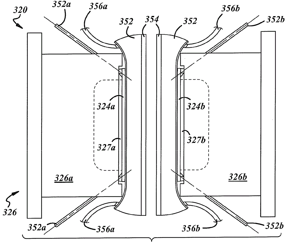
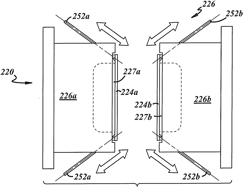
[0030] See the attached drawings in more detail, figure 1 An exemplary embodiment of the mold forming apparatus 20 is described, which can be used to implement the method of manufacturing a single-layer or multi-layer plastic product (such as a plastic fuel tank) of the present disclosure. During the manufacturing of the product, one or more The components are introduced into the product. The following device description only provides a brief overview of an exemplary device, but other devices not shown here can also support the currently disclosed method.

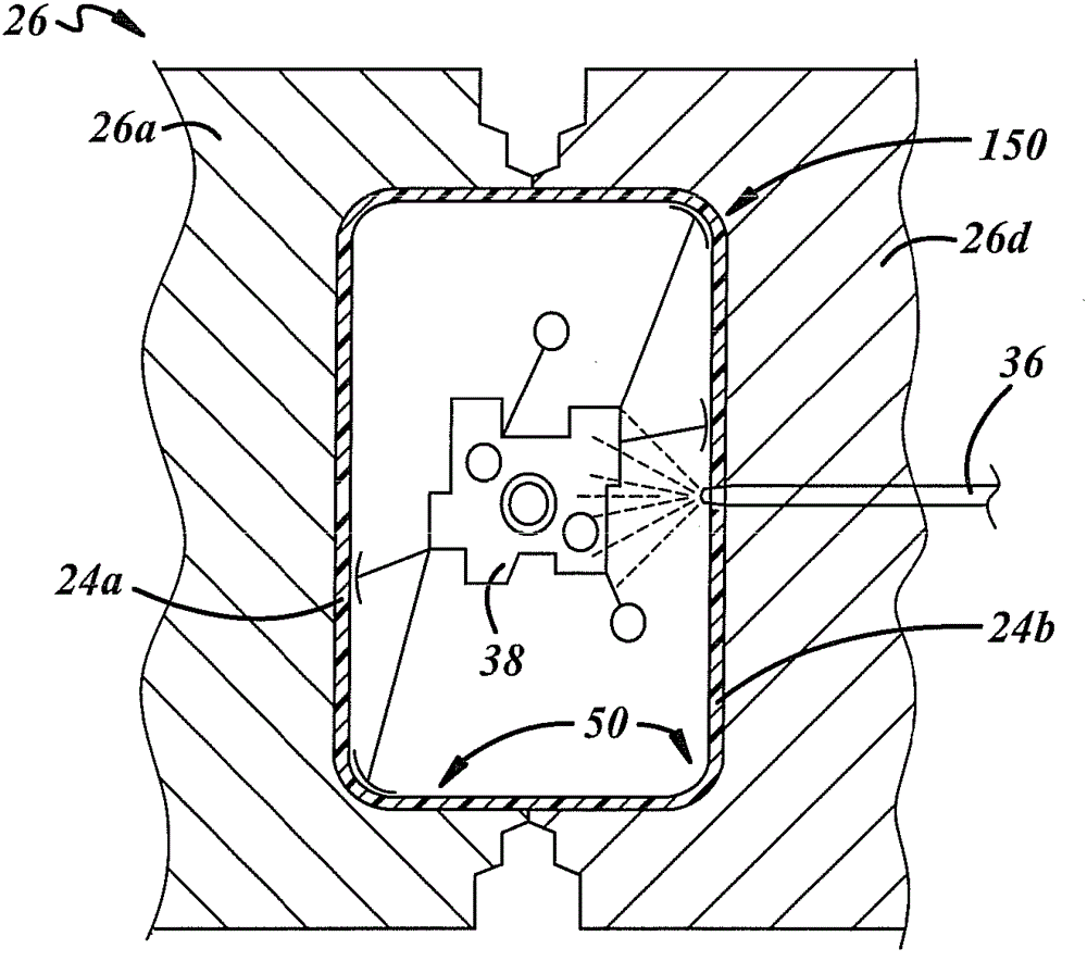
[0031] Generally speaking, the equipment 20 may include an extruder 22 for producing the parison 24, and a die 26 of a blow molding and / or deep drawing machine to form the parison 24 into a product, such as a fuel tank (not shown) , And the mold includes substantially opposed mold halves 26a, 26b. As used herein, the term "mold half" can include a single component or a multi-component assembly. In other words, each mold half...


PUM

PropertyMeasurementUnit
melting pointaaaaaaaaaa

Abstract

A method of manufacturing a product comprising extruding a parison; dividing said parison into parison halves by cutting a partially expanded parison or pulling apart a longitudinally weakened parison; and forming the formed parison against respective mold halves. Describe the parison half. The method may further comprise applying a film against the parison half and / or the mold half; and forming the film and parison half against the mold half to produce a multilayer product half. An apparatus for performing the method is also disclosed.

Description

Technical field [0001] The present invention relates generally to a method of producing a plastic container, and more specifically to a molding process of a plastic product. Background technique [0002] Blow molding is a well-known method for producing various plastic products, especially containers or hollow vessels including fuel tanks, reservoirs, etc. In general, the typical blow molding process for a multilayer fuel tank involves extruding a multilayer tubular parison around the expander rod and the blow rod in an open mold. The spreader rod expands so that the hot parison is half-extended radially toward the mold. The mold halves are closed together around the stretched parison, and the blow pin injects pressurized gas into the parison to make the parison conform to the inner surface of the mold half. At the same time, the bracket and various fuel system components, such as fuel quantity sensors, ventilation devices, fuel pumps, fuel filters, etc., can be carried by the ...

Claims


Application Information

Patent Timeline
Patent Type & Authority Patents(China)
IPC IPC(8): B29C49/02B29C65/02B29C51/02B29C51/06B29C48/09B29C48/10B29C48/151B29C48/19B29C48/92
CPCB29C49/04B29C49/20B29C49/22B29C49/4205B29C49/4247B29C51/267B29C65/028B29C65/18B29C65/5057B29C66/1142B29C66/1312B29C66/54B29C2049/2008B29C2791/006B29C2793/00B29C2793/0063B29C2793/0081B29K2995/0069B29L2009/00B29L2031/7172B29C65/5021B29C65/4815B29C66/83221B29C66/7234B29C66/72321B29C66/71B29C66/8242B29C48/92B29C48/09B29C48/10B29C48/0017B29C48/0022B29C48/151B29C48/19B29C2948/92514B29C2948/92809B29C2948/92923B29C2049/7831B29C2049/7832B29K2077/00B29K2059/00B29K2023/086B29K2023/065B29K2023/0625B29K2023/06B29K2021/003
Inventor A.J.贝克A.W.多布迈尔A.埃勒P.格明德P.格劳尔M.豪亚拉M.B.奥尔布里奇P.E.德尔巴勒
Owner TI AUTOMOTIVE TECH CENT
Why Eureka
Try Eureka