Internal combustion engine

A technology for internal combustion engines and burners, which is applied to internal combustion piston engines, combustion engines, mechanical equipment, etc., and can solve problems such as warming up difficult small oxidation catalysts and exhaust treatment devices

Inactive Publication Date: 2012-11-28
TOYOTA JIDOSHA KK
View PDF5 Cites 3 Cited by
  • Summary
  • Abstract
  • Description
  • Claims
  • Application Information

AI Technical Summary

Problems solved by technology

Therefore, it is difficult to efficiently warm up the small oxidation catalyst and the exhaust gas treatment device.

Method used


Image

  • Internal combustion engine
  • Internal combustion engine
  • Internal combustion engine

Examples


Embodiment Construction

[0033] Preferred embodiments of the present invention will be described in detail below. However, it should be noted that the embodiments of the present invention are not limited to the following aspects, and the present invention includes all modifications and application examples included in the concept of the present invention defined by the claims. The dimensions, materials, shapes, and relative arrangements of components described in the embodiments are not limited to the technical scope of the invention unless otherwise specified.

[0034] In the following description, the upstream side is also referred to as "front", and the downstream side is also referred to as "rear".

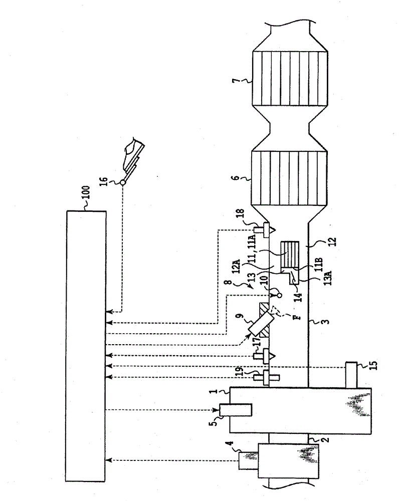
[0035] figure 1 The schematic structure of the internal combustion engine (engine) in this embodiment is shown. The engine is a vehicle-mounted 4-stroke diesel engine. An intake pipe 2 forming an intake passage and an exhaust pipe 3 forming an exhaust passage are connected to the engine body 1 . I...


PUM


Abstract

An internal combustion engine according to the present invention is equipped with an exhaust treatment device provided in an exhaust passage, and a burner device provided upstream of the exhaust treatment device. The burner device includes: a fuel addition valve that adds fuel to the exhaust passage; a heating device that heats the fuel added from the fuel addition valve; and a small oxidation catalyst that is provided in the exhaust passage downstream of the heating device. The amount of fuel to be added from the fuel addition valve per prescribed unit time is controlled, thereby controlling the position of the ignition point at which the added fuel ignites. The small oxidation catalyst and the exhaust treatment device can thus be efficiently warmed up.

Description

technical field [0001] The present invention relates to an internal combustion engine, and more particularly, to an internal combustion engine provided with a burner device for raising the temperature of the exhaust gas on the upstream side of an exhaust treatment device in an exhaust passage. Background technique [0002] In the exhaust passage of the internal combustion engine, a burner device is sometimes installed on the upstream side of the exhaust treatment device (catalyst, etc.), and the temperature of the exhaust gas is raised by the heating gas generated by the burner device, and the exhaust treatment device is heated to promote Warming up of the exhaust treatment unit. A typical burner device generates heated gas including a flame by igniting and burning fuel added to the exhaust passage. In some cases, a small oxidation catalyst is provided in the exhaust passage, and the added fuel is reformed or combusted by the small oxidation catalyst. [0003] For example,...

Claims


Application Information

Patent Timeline
Patent Type & Authority Applications(China)
IPC IPC(8): F01N3/36F01N3/02F01N3/20F01N3/24F02D45/00
CPCF01N2610/03F01N3/38F01N2610/146F02D41/1446F01N3/2033F02D2200/0804Y02T10/47F01N2900/1621F01N3/106F01N3/103F02D41/1441F01N9/00F02D41/068Y02T10/26F01N3/0256F01N2240/20Y02T10/12Y02T10/40
Inventor 布施英孝
Owner TOYOTA JIDOSHA KK
Why Eureka
Try Eureka