Automatic splicing machine for joints of steel wire cords

A technology of automatic splicing and steel cord, which is applied to tires, other household appliances, household appliances, etc., can solve the problems of easy misalignment of joints, long sequence time, and poor quality, so as to achieve less deviation, improve production efficiency, and save energy. The effect of manufacturing costs

Active Publication Date: 2012-12-05
桂林中昊力创机电设备有限公司
View PDF3 Cites 11 Cited by
  • Summary
  • Abstract
  • Description
  • Claims
  • Application Information

AI Technical Summary

Problems solved by technology

[0003] The traditional cutting and splicing equipment process is divided into four servo conveyor belts from cutting and unloading, splicing feeding,

Method used


Image

  • Automatic splicing machine for joints of steel wire cords

Examples


Embodiment Construction

[0021] Below in conjunction with accompanying drawing, technical scheme of the present invention is described further:

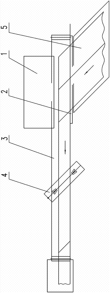
[0022] The automatic splicing machine for steel cord joints of the present invention is mainly composed of a clamping and transferring device 1 , a cutting device 2 , a servo conveyor belt 3 and a splicing device 4 .

[0023] The servo conveyor belt 3 is placed horizontally in the left and right directions, and the right end is the starting end of the servo conveyor belt 3; The conveyor belt 3 is set; the clamping and transferring device 1 composed of two-axis servo-driven pneumatic clamping rods is installed behind the cutting device 2; the cord 5 is arranged in front of the cutting device 2, and the arrangement direction of the cord 5 is perpendicular to the servo conveyor belt 3 The longitudinal direction; the splicing device 4 is arranged above the servo conveyor belt 3 through the screw nut transmission mechanism, the screw direction of the screw nut tr...


PUM


Abstract

The invention relates to an automatic splicing machine for joints of steel wire cords. The automatic splicing machine comprises a cord clamping and transferring device, a cutting device, a servo conveying belt and a splicing device. The cutting device is arranged on a side surface of a starting end of the servo conveying belt, the cord clamping and transferring device is arranged behind the cutting device, the cord conveying direction of the cord clamping and transferring device is perpendicular to the servo conveying belt, stepping of the servo conveying belt is set according to the length of a cut cord, the splicing device is arranged above the servo conveying belt via a moving mechanism, and the splicing position of the splicing device corresponds to a cord lap-joint position or a seam position of the cord which is discharged out of a cord cutting and transferring area according to the step. Compared with an original cutting machine in a splicing mode, the automatic splicing machine has the advantages that a feeding conveying belt and a splicing conveying belt are omitted, and functions such as feeding and splicing are executed on the servo conveying belt.

Description

(1) Technical field: [0001] The invention relates to an auxiliary equipment for manufacturing rubber tires, in particular to an automatic splicing machine for steel cord joints. (2) Background technology: [0002] The traditional steel cord cutting and splicing equipment includes a cloth transfer device, a cutting device, a cord conveying device after cutting, a feeding and conveying device before splicing, an independent splicing conveyor belt, a splicing device and a splicing unloading device. The fixed-length material is fed to the cutting device. After cutting, the cord conveying device picks up the cut cord and sends it to the feeding conveying device before splicing. The head is positioned on the splicing conveyor belt for splicing. After splicing, the cord is unloaded, and the tail is positioned on the splicing conveyor belt. . [0003] The traditional cutting and splicing equipment process is divided into four servo conveyor belts from cutting and unloading, splicin...

Claims


Application Information

Patent Timeline
IPC IPC(8): B29D30/38
Inventor 李德昌
Owner 桂林中昊力创机电设备有限公司
Why Eureka
Try Eureka