
Supporting insulation structure for refuge chamber of deep well under high-temperature geological conditions

A technology for geological conditions and refuge chambers, applied in safety devices, mining equipment, earthwork drilling and mining, etc., can solve problems such as difficult cooling power to adjust chamber temperature, and achieve the effect of reducing heat load

Inactive Publication Date: 2012-12-05
HEFEI DESIGN & RES INST LLC OF COAL IND
View PDF7 Cites 1 Cited by
  • Summary
  • Abstract
  • Description
  • Claims
  • Application Information

AI Technical Summary

Problems solved by technology

Due to the high-temperature geological conditions of deep wells in some mines, a large amount of rock temperature and geothermal heat will be transmitted to the interior of the refuge chamber through the support structure layer of the refuge chamber. Human body can accept

Method used


Image

  • Supporting insulation structure for refuge chamber of deep well under high-temperature geological conditions
  • Supporting insulation structure for refuge chamber of deep well under high-temperature geological conditions

Examples


Embodiment 1

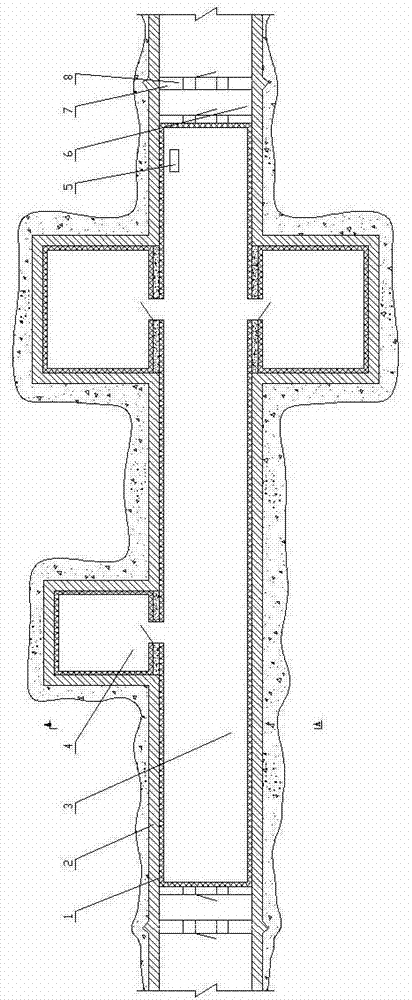
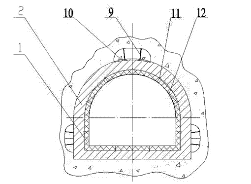
[0019] The surrounding rock around the refuge chamber is first supported by anchor rods 9, steel mesh 10 and sprayed layer, and then the concrete structure layer 2 is built to ensure the stability of the shape of the chamber. On this basis, according to the rock temperature conditions and the living environment temperature required by the refuge chamber, the thickness of the insulation layer is preliminarily determined to be 50-300mm. The specific value of the thickness is initially selected during design, the heat transfer is calculated according to the parameters of the polyurethane material, and the cooling equipment is selected. According to the equipment selection results, optimize the insulation thickness and equipment selection matching technical scheme.

[0020] During the construction of the insulation layer, the formwork is used to lay the polyurethane material on the inner surface of the chamber. After the material is formed, in order to ensure that the insulation ...

Embodiment 2

[0022] Anchor mesh spraying, concrete construction and other methods are adopted around the refuge chamber to ensure the stability of the chamber shape. On this basis, according to the rock temperature conditions and the living environment temperature required by the refuge chamber, the thickness of the insulation layer is preliminarily determined to be 50-300mm. The specific value of the thickness is initially selected during the design, and the heat transfer is calculated according to the parameters of the thermal insulation material, that is, the foamed cement prefabricated block, and the cooling equipment is selected. According to the equipment selection results, optimize the insulation thickness and equipment selection matching technical scheme.

[0023] Before the construction of the insulation layer, prefabricated foamed cement insulation blocks according to the shape of the chamber, or customized from professional building insulation materials. During construction, th...


PUM

PropertyMeasurementUnit
Thicknessaaaaaaaaaa

Abstract

The invention relates to a supporting insulation structure for a refuge chamber of a deep well under high-temperature geological conditions. The supporting insulation structure comprises a concrete structure layer built around enclosing rock, and an insulation layer is arranged at the inner side of the concrete structure layer. The insulation layer has the thickness of 50-300 mm and is made from polyurethane insulation materials or foamed cement prefabricated building blocks. According to the supporting insulation structure for the refuge chamber of the deep well under the high-temperature geological conditions, heat of high-temperature rock is enabled to be difficultly transferred to the refuge chamber, so that the heat load of the refuge chamber required for being cooled through air conditioning is obviously reduced, and the condition that the indoor temperature of the chamber can be conditioned to the temperature acceptable to human bodies through a conventional cooling manner becomes possible.

Description

technical field [0001] The invention relates to a support and heat preservation structure of an emergency refuge chamber in the field of mines, in particular to a heat preservation structure of a refuge chamber under high-temperature geological conditions in deep wells. [0002] Background technique [0003] Mine mines mined by underground workers often need to be equipped with emergency refuge chambers. The refuge chamber is a closed space, which is used to provide a temporary shelter for refugees after a mine accident occurs. The chamber is equipped with oxygen supply and adjustment, air purification, air curtain, temperature and humidity adjustment, emergency lighting, communication, food, water and other basic configurations required for personnel to avoid danger and survive. Due to the high-temperature geological conditions of deep wells in some mines, a large amount of rock temperature and geothermal heat will be transmitted to the interior of the refuge chamber thro...

Claims


Application Information

Patent Timeline
IPC IPC(8): E21F11/00
Inventor 闫红新秦强陆传宗马乾坤吴双白
Owner HEFEI DESIGN & RES INST LLC OF COAL IND
Learn More