
Battery pole piece cutting-off equipment and battery pole piece cutting-off method

A technology for battery pole pieces and cutting equipment, which is applied in electrode manufacturing and other directions, can solve the problems of complex battery manufacturing process, easy sticking of materials, contamination of the knife edge, etc., to avoid sticking and contamination of the knife edge, simplify the production process, and avoid the effect of pollution.

Active Publication Date: 2012-12-05
FUJIAN NANPING NANFU BATTERY
View PDF6 Cites 4 Cited by
  • Summary
  • Abstract
  • Description
  • Claims
  • Application Information

AI Technical Summary

Problems solved by technology

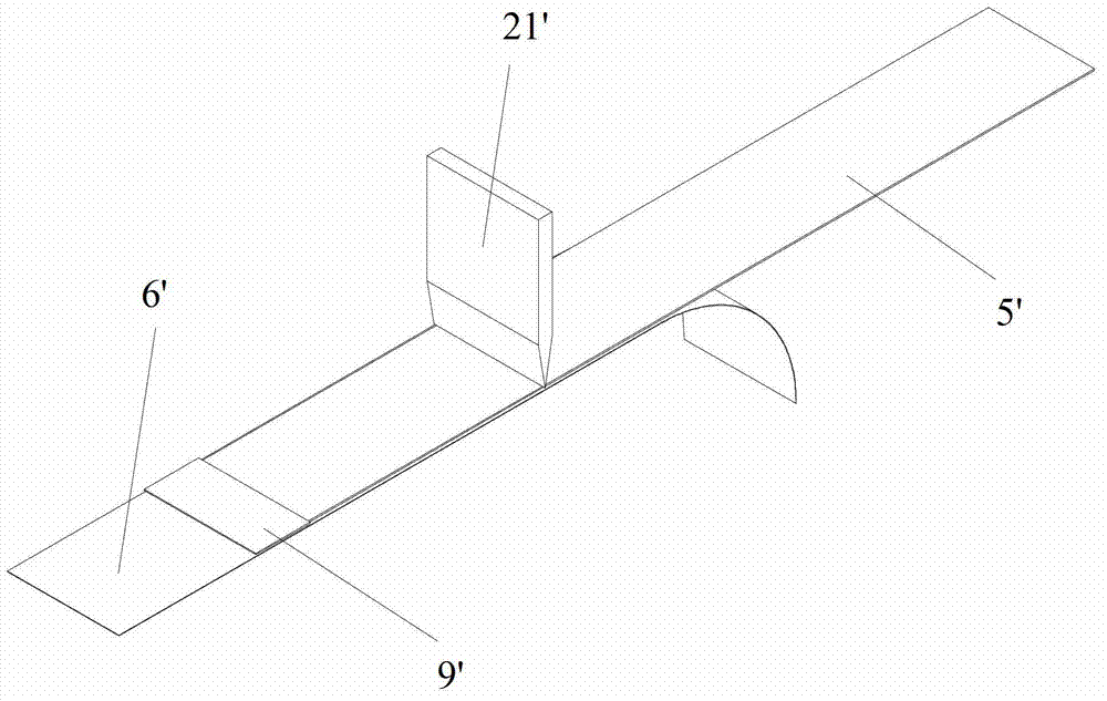
It can be understood that in the prior art, when cutting the pole piece 5', the edge of the cutter 21' directly contacts the pole piece 5', and the pole piece 5' is generally made of a soft metal material (such as lithium or lithium alloy), so that it is extremely Material on sheet 5' tends to stick to the knife edge and contaminate the knife edge
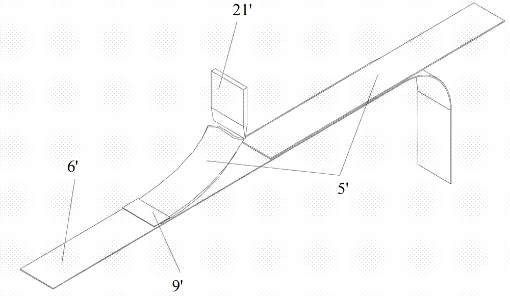
In addition, if figure 2 As shown, since the pole piece 5' is relatively soft, when the cutter 21' moves upward after cutting off the pole piece 5', it may also lift up the end of the cut off pole piece 5', causing it to deform
And as mentioned above, each pole piece 5' needs to be fixed with the separator 6' by the adhesive tape 9', which makes the manufacturing process of the battery more complicated

Method used


Image

  • Battery pole piece cutting-off equipment and battery pole piece cutting-off method
  • Battery pole piece cutting-off equipment and battery pole piece cutting-off method
  • Battery pole piece cutting-off equipment and battery pole piece cutting-off method

Examples


Embodiment Construction

[0030] In the following description, numerous specific details are given in order to provide a more thorough understanding of the present invention. It will be apparent, however, to one skilled in the art that the present invention may be practiced without one or more of these details. In other examples, some technical features known in the art are not described in order to avoid confusion with the present invention.

[0031] In order to provide a thorough understanding of the present invention, the detailed structure will be set forth in the following description. It is evident that the practice of the invention is not limited to specific details familiar to those skilled in the art. Preferred embodiments of the present invention are described in detail below, however, the present invention may have other embodiments besides these detailed descriptions.

[0032] Such as image 3 and Figure 4 As shown, the battery pole piece cutting device according to the first embodimen...


PUM


Abstract

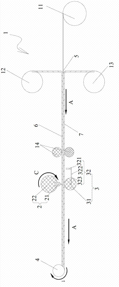
The invention discloses battery pole piece cutting-off equipment and a battery pole piece cutting-off method. The battery pole piece cutting-off equipment comprises a feeding device, a cutting knife device, a supporting device and a coiling device, wherein the feeding device is used for sending out a first diaphragm, a pole piece and a second diaphragm which are sequentially overlapped at the same feeding speed; the cutting knife device is arranged at the downstream of the feeding device and comprises a knife rest and a cutting knife fixed on the knife rest; the knife rest is used for pressing the cutting knife towards the first diaphragm by moving or autorotating and cutting off only the pole piece from the first diaphragm side by being separated by the first diaphragm; the supporting device is opposite to the cutting knife device by being separated by the first diaphragm, the pole piece and the second diaphragm so as to support the cutting knife below the second diaphragm when the cutting knife is pressed towards the first diaphragm; and the coiling device is arranged at the downstream of the cutting knife device and is used for coiling the first diaphragm, the cut-off pole piece and the second diaphragm together. The battery pole piece cutting-off equipment can avoid adhesion of the pole piece to a knife edge of the cutting knife and pollution to the knife edge, avoid deformation of the pole piece, and omit a step of fixing the pole piece and the diaphragm through an adhesive tape, thus simplifying the manufacturing process of a battery.

Description

technical field [0001] The invention relates to the technical field of chemical power sources, in particular to a battery pole piece cutting device and a battery pole piece cutting method. Background technique [0002] The manufacturing method of the battery includes the process of stacking and winding the pole piece and the diaphragm to form a battery core. In the process of forming the battery cell, the pole piece needs to be cut to a required length, and the end of the cut pole piece needs to be fixed to the separator. Such as figure 1 As shown, the pole piece 5' from the feeding device (not shown) is cut by the cutting knife 21' from top to bottom to have the required length, and the end of each cut pole piece 5' is passed through The tape 9' is secured to the membrane 6'. It can be understood that in the prior art, when cutting the pole piece 5', the edge of the cutter 21' directly contacts the pole piece 5', and the pole piece 5' is generally made of a soft metal ma...

Claims


Application Information

Patent Timeline
Patent Type & Authority Applications(China)
IPC IPC(8): H01M4/04B23D79/00
CPCY02E60/12Y02E60/10
Inventor 陈进添常海涛赵洋苏盛张清顺
Owner FUJIAN NANPING NANFU BATTERY
Learn More