
Visual prosthesis image acquisition device on basis of eye tracking

An image acquisition device and visual prosthesis technology, applied in the field of biomedical engineering, can solve the problems of not being able to make full use of human eyes to quickly search and locate, and achieve a good user experience

Active Publication Date: 2012-12-12
SHANGHAI JIAO TONG UNIV
View PDF3 Cites 24 Cited by
  • Summary
  • Abstract
  • Description
  • Claims
  • Application Information

AI Technical Summary

Problems solved by technology

It can be seen that the visual prostheses of the prior art do not well realize the bionics of human vision and eye movement functions, and cannot make full use of the physiological characteristics of the human eye to quickly search and locate the target through eye movement

Method used


Image

  • Visual prosthesis image acquisition device on basis of eye tracking
  • Visual prosthesis image acquisition device on basis of eye tracking
  • Visual prosthesis image acquisition device on basis of eye tracking

Examples


Embodiment Construction

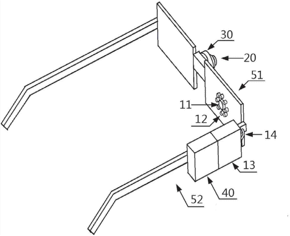
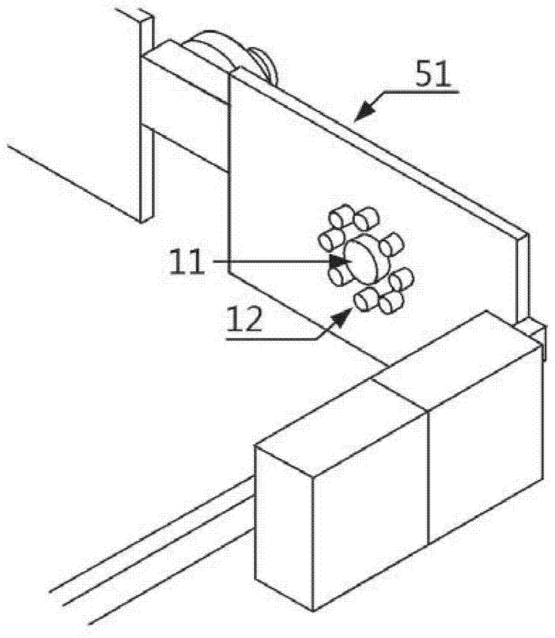
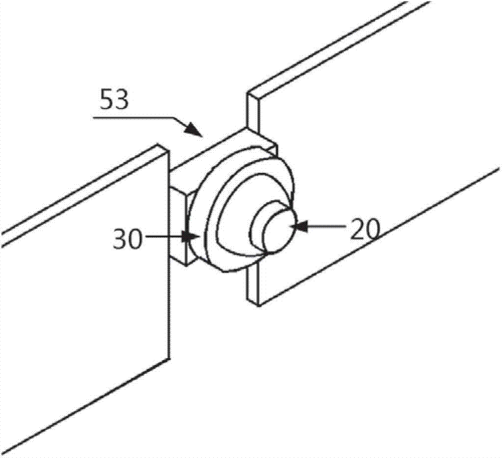
[0024] Such as Figure 1-3 As shown, in one embodiment of the present invention, the image acquisition device of the visual prosthesis of the present invention is set on the sunglasses worn by the blind patient, and includes an eye movement signal acquisition and processing module, a camera 20 and a rotating platform 30 . Wherein, the camera 20 is fixed on the rotating platform 30, and the rotating platform 30 is arranged on the bridge of the nose 53 of the sunglasses. The camera 20 is facing outwards (that is, facing away from the patient wearing the sunglasses), and the pan-tilt 30 is rotated to receive the control signal sent by the eye movement signal acquisition and processing module and rotate accordingly. When it rotates, it will drive the camera 20 to rotate together .

[0025] The eye movement signal acquisition and processing module includes an eye movement camera 11 , an LED unit 12 , an eye movement video receiving and processing unit 13 and a data line 14 . Wher...


PUM

PropertyMeasurementUnit
Outer diameteraaaaaaaaaa
Angle of viewaaaaaaaaaa

Abstract

The invention discloses a visual prosthesis image acquisition device which comprises an eye movement acquiring and processing module, a camera and a rotating cradle head. The eye movement acquiring and processing module is used for acquiring an eye movement signal of an eyeball and sending a control signal according to the signal to control the rotation of the rotating cradle head so as to ensure the camera fixed on the rotating cradle head to turn to the rotation direction of the eyeball and acquire an image in the direction, wherein the eye movement acquiring and processing module comprises an eye movement camera for shooting a video of movement of a pupil of the eyeball and an eye movement video receiving and processing unit for receiving the video and acquiring the rotation direction of the eyeball by the video. According to the invention, by acquiring the rotation direction of the eyeball in real time so as to control the rotating cradle head to drive the camera to turn to the direct and acquire the image in the direction, the biomimetics on human vision and eye movement functions is well implemented, so that a user acquires the prosthesis visual experience closer to the normal vision.

Description

technical field [0001] The invention relates to the field of biomedical engineering, in particular to an image acquisition device for visual prosthesis based on eye movement tracking. Background technique [0002] A visual prosthesis is an implanted medical electronic device that restores some degree of vision to severely blind patients. It takes advantage of the fact that most blind patients often only have a part of the visual pathway with lesions, while the structure and function of the rest of the nervous tissue are still intact, and applies specific artificial electrical stimulation to the intact part of the visual pathway to excite nerve cells, simulating natural light stimulation. The effect allows the user to have a visual experience. The visual prosthesis system usually includes an image acquisition device located outside the user's body (usually a miniature camera), an image processing device, an electrical stimulation coding device, and a microelectrode array imp...

Claims


Application Information

Patent Timeline
IPC IPC(8): A61F9/08H04N5/232
Inventor 柴新禹吴开杰古陨雷旭平
Owner SHANGHAI JIAO TONG UNIV
Learn More