
Device for removing surface attachment of steel shovel

A technology of attachments and shovels, applied in the field of equipment for removing dirt, can solve problems such as affecting the normal work and rest of surrounding residents, injury to operators and surrounding residents, and pollution of surrounding air and land, so as to eliminate occupational diseases and reduce product cost, the effect of avoiding pollution

Active Publication Date: 2012-12-12
TANGSHAN YANNAN SHOVEL MAKING
View PDF7 Cites 9 Cited by
  • Summary
  • Abstract
  • Description
  • Claims
  • Application Information

AI Technical Summary

Problems solved by technology

Most of the traditional barrels are punched on the wall of the barrel. When in use, a steel shovel is installed inside the barrel, and then a certain amount of iron abrasives are added. The motor drives the barrel to rotate. When the equipment is normally started for a certain period of time, the oxide scale and other substances produced on the surface of the steel shovel will be separated by the friction between the iron abrasive and the steel shovel, and the separated iron powder will fly out of the barrel from the hole in the barrel wall. In addition, it cannot be recycled and reused, and the surrounding air and land are seriously polluted
During the working process of the equipment, due to the mutual friction between the steel shovel and the iron abrasive, the noise generated is very serious, which affects the normal work and rest of the surrounding residents, and brings great harm to the operator and the surrounding residents. Cause deafness, tinnitus and other occupational diseases to users

Method used


Image

  • Device for removing surface attachment of steel shovel
  • Device for removing surface attachment of steel shovel
  • Device for removing surface attachment of steel shovel

Examples


Embodiment Construction

[0014] The present invention will be further described below in conjunction with the accompanying drawings.

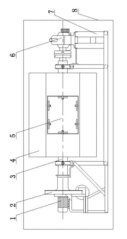
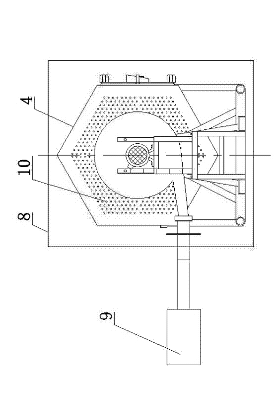
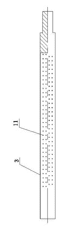
[0015] See attached Figure 1-4 The device for removing attachments on the surface of the steel shovel disclosed in the present invention includes a frame 7, a transmission motor 12 and a speed reducer 6 connected together are mounted on the frame 7, and the bucket 4 is arranged in the middle of the frame 7 and runs through the One end of the barrel shaft 3 of the barrel 4 is connected with the reducer 6 through a bearing and a shaft coupling, the barrel shaft 3 is a hollow structure, and dust removal holes 11 are evenly distributed on the side walls of the barrel shaft 3 . An induced draft fan 2 is arranged on the frame 7, one side of the induced draft fan is connected with the induced draft fan motor 1, the air inlet of the induced draft fan 2 communicates with the other end of the barrel shaft 3, and the other end of the barrel shaft 3 is also passed through a beari...


PUM


Abstract

The invention relates to a device for removing the surface attachment of a steel shovel; the device comprises a frame, and a transmission motor and a reducing gear which are arranged on the frame and are connected together; a barrel is arranged at the middle part of the frame; one end which penetrates through the barrel shaft of the barrel is connected with the reducing gear through a bearing and a coupler; the barrel shaft is in a hollow structure; dust removal holes are uniformly distributed on the side wall of the barrel shaft; a draught fan is arranged on the frame; the air inlet of the draught fan is communicated with the other end of the barrel shaft; and the outer side of the frame is provided with a cyclone separator which is communicated with the air outlet of the draught fan. According to the device for removing the surface attachment of the steel shovel, the structure is simple, the surface attachment of the steel shovel is removed, meanwhile iron powder does not fly everywhere, the removed iron powder can be recovered in time, and a role of protecting the environment is played. The device is arranged in a sound-proof room with sound-proof boards, so that an operator is not harmed by the noise, the environment is not polluted, the product cost is reduced, and the economic benefits are improved.

Description

technical field [0001] The invention relates to a device for removing dirt, in particular to a device for removing attachments on the surface of a steel shovel, which can separate the iron powder attached to the surface of the steel shovel from the body of the steel shovel and recover the iron powder in real time Reuse. Background technique [0002] At present, the commonly used device for removing the attachments on the surface of the steel shovel is a bucket, which has the function of cleaning the iron powder attached to the surface of the steel shovel. Most of the traditional barrels are punched on the wall of the barrel. When in use, a steel shovel is installed inside the barrel, and then a certain amount of iron abrasives are added. The motor drives the barrel to rotate. When the equipment is normally started for a certain period of time, the oxide scale and other substances produced on the surface of the steel shovel will be separated by the friction between the iron ...

Claims


Application Information

Patent Timeline
Patent Type & Authority Applications(China)
IPC IPC(8): B24B31/02B24B31/12
Inventor 付长强宿革震
Owner TANGSHAN YANNAN SHOVEL MAKING
Learn More