
Water spray type steam compressor

A steam compressor and water spray technology, which is applied in the direction of liquid variable volume machinery, mechanical equipment, engine functions, etc., can solve problems such as difficulty in grasping the state of wet steam

Active Publication Date: 2012-12-12
코벨코컴프레서가부시키가이샤
View PDF9 Cites 4 Cited by
  • Summary
  • Abstract
  • Description
  • Claims
  • Application Information

AI Technical Summary

Problems solved by technology

In Patent Document 1, a thermometer and a pressure gauge are installed in the suction pipe of the compressor, but it is difficult to grasp the state quantity (specific enthalpy) of the wet steam only by the thermometer and the pressure gauge.

Method used


Image

  • Water spray type steam compressor

Examples


Embodiment Construction

[0026] Hereinafter, modes for implementing the present invention will be described with reference to the drawings.

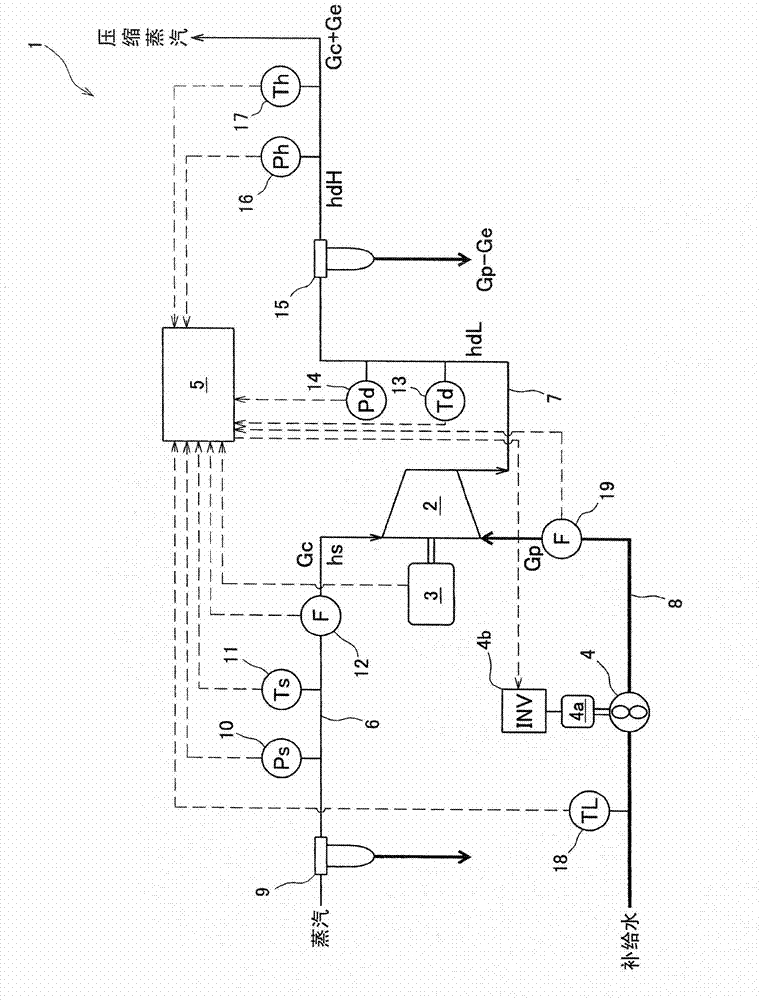
[0027] (Structure of water jet steam compressor)

[0028] Such as figure 1 As shown, a water jet steam compressor 1 includes a screw compressor 2 that compresses and discharges steam, a motor 3 that drives the screw compressor 2 , a water jet pump 4 , and a control unit 5 that controls the water jet pump 4 . The water jet pump 4 is driven by an electric motor 4a, and the rotational speed of the electric motor 4a is controlled by an inverter 4b. The water jet pump 4 corresponds to the water supply mechanism of the present invention. It should be noted that it may also be a rotary compressor, a scroll compressor, a Roots compressor, etc. instead of a screw compressor.

[0029] A suction pipe 6 and a discharge pipe 7 are connected to the screw compressor 2 . The suction pipe 6 is a path for supplying steam to be compressed to the screw compressor 2 , and the di...


PUM


Abstract

The present invention provides a water spray type steam compressor, which has a structure capable of accurately grasping the temperature of supply water and quantity state of the suction steam. The structure can help to prevent the sprayed steam from changing into superheated steam, and prevent the quantity of the sprayed steam from reducing. The water spray type steam compressor (1) is provided with a suction side drain water separator (9) arranged on a suction tube (6), a water injection pump (4) which sprays the supply water into the compression space inside a screw compressor (2), a supply water thermometer (18) for the detection of the temperature of the supply water, and a control part (5) used for controlling the injection quantity of the supply water. According to the specific enthalpy of the suction steam flowing in the suction tube (6) downstream side of the suction side drain water separator (9) and the specific enthalpy of the supply water calculated from the detection value of the supply water thermometer (18), the control part (5) controls the injection quantity of the supply water in a way of equaling the surplus output energy of the screw compressor (2) to the gasification heat of the supply water, wherein the surplus output energy equals that the total output energy minus the energy consumption of boosting the pressure of the suction steam up to prescribed injection pressure.

Description

technical field [0001] The present invention relates to a water spray type steam compressor including a water supply mechanism for spraying water into at least one of a compression space inside a compressor and a suction pipe connected to the compressor. Background technique [0002] As a technique for controlling the water injection amount in the water injection steam compressor, there is a technique described in Patent Document 1, for example. The control technique described in Patent Document 1 is a technique of using, among the energy given to the steam by the compressor, the thermal energy remaining after the energy is consumed to increase the pressure of the steam sucked by the compressor to its discharge pressure, as heat energy for introducing water. (Make-up water) is consumed by latent heat of vaporization to form a required amount of introduced water (make-up water) sufficient to cause steam to be ejected from the compressor in the state of wet steam partially in ...

Claims


Application Information

Patent Timeline
IPC IPC(8): F04C29/00
CPCF04B41/02F04B49/22F04B53/06F05B2210/12F05B2260/60Y10S417/00
Inventor 桑原英明宫武利幸松隈正树
Owner 코벨코컴프레서가부시키가이샤
Learn More