
Clutch torque trajectory correction to provide torque hole filling during a ratio upshift

A technology of torque stage and input torque, which is applied in the field of multi-speed transmission mechanism, can solve the problems of uncomfortable shifting shock and other problems, and achieve the effect of seamless transition, improved performance and predictability, and accurate adjustment

Active Publication Date: 2012-12-12
FORD GLOBAL TECH LLC
View PDF10 Cites 16 Cited by
  • Summary
  • Abstract
  • Description
  • Claims
  • Application Information

AI Technical Summary

Problems solved by technology

This results in an uncomfortable shift shock felt by the vehicle occupants

Method used


Image

  • Clutch torque trajectory correction to provide torque hole filling during a ratio upshift
  • Clutch torque trajectory correction to provide torque hole filling during a ratio upshift
  • Clutch torque trajectory correction to provide torque hole filling during a ratio upshift

Examples


Embodiment Construction

[0023] As required, detailed embodiments of the present invention are disclosed herein; however, it is to be understood that the disclosed embodiments are merely exemplary of the invention, which may be embodied in various and alternative forms. The figures are not necessarily to scale; some features may be exaggerated or minimized to show details of particular components. Therefore, specific structural and functional details disclosed herein are not to be interpreted as limiting, but merely as a representative basis for teaching one skilled in the art to variously employ the present invention.

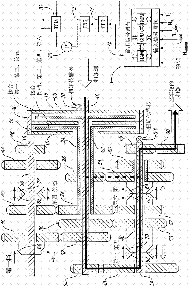
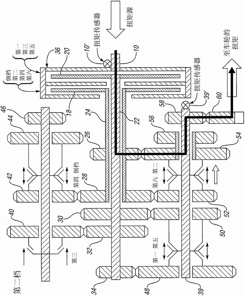
[0024] figure 1 A countershaft type transmission capable of implementing the present invention is shown in a schematic form, as well as a schematic diagram of the transmission components involved in gear change.

[0025] Reference numeral 10 denotes a power input shaft drivably connected to a torque source 12 . The input shaft 10 drives the clutch housing 14 , the clutch housing 14 ...


PUM


Abstract

A control system and method for controlling a multiple gear ratio automatic transmission in a powertrain for an automatic transmission having pressure activated friction torque elements to effect gear ratio upshifts. The friction torque elements are synchronously engaged and released during a torque phase of an upshift event as torque from a torque source is increased while allowing the off-going friction elements to slip, followed by an inertia phase during which torque from a torque source is modulated. A perceptible transmission output torque reduction during an upshift is avoided. Measured torque values are used during a torque phase of the upshift to correct an estimated oncoming friction element target torque so that transient torque disturbances at an oncoming clutch are avoided and torque transients at the output shaft are reduced.

Description

technical field [0001] The present invention relates to a multi-speed transmission mechanism in a powertrain of an automated vehicle and a strategy to achieve smooth engagement and disengagement of friction torque building elements during upshifts. Background technique [0002] A stepped automatic transmission utilizes multiple friction elements to automatically shift gears. A gear change from low to high occurs during a synchronized clutch-to-clutch upshift when one friction element engages and the other disengages. The one friction element may be referred to as an offgoing clutch (OGC). The one friction element is disengaged while the other friction element, which may be referred to as an oncoming clutch (OCC), is engaged to effect an upshift. The upshift event is divided into a preparation phase, a torque phase and an inertia phase. During the preparation phase, the OCC actuator is activated in preparation for engagement of the OCC while the torque capacity held by the...

Claims


Application Information

Patent Timeline
Patent Type & Authority Applications(China)
IPC IPC(8): F16H59/16
CPCB60W10/115F16H2061/0462F16H61/061B60W10/02F16D67/02F16H59/16F16H61/68F16H61/06F16H61/0403B60W10/06B60W30/19B60W50/06B60W2050/0008B60W2050/0043B60W2510/0275B60W2510/105B60W2710/025B60W2710/027B60W2710/0666B60W2710/105
Inventor 克里斯多佛·约翰·泰斯拉克格雷戈里·迈克尔·皮尔准恩鸿泰·埃里克·曾藤井雄二迈克尔·格伦·福德黛安娜·雅娜奇维夫李承勋
Owner FORD GLOBAL TECH LLC
Learn More