

Electromagnetic positioning splicing apparatus and method for coded light three-dimensional measurement
An electromagnetic positioning and three-dimensional measurement technology, applied in the field of coded light three-dimensional measurement, achieves the effect of low structural strength requirements, reduced volume, and simple structure
- Summary
- Abstract
- Description
- Claims
- Application Information
AI Technical Summary
Problems solved by technology
Method used
Image

Examples
Embodiment Construction
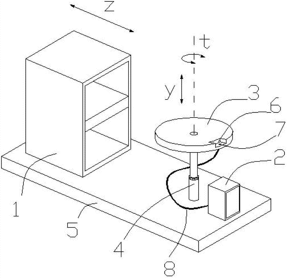
[0026] Below in conjunction with accompanying drawing and specific embodiment the present invention will be further described:
[0027] combine figure 1 , The electromagnetic positioning splicing device for coded light three-dimensional measurement in this embodiment includes a measuring unit frame 1 , a splicing unit frame 2 , a circular stage 3 , a support column 4 , and a base 5 . The upper surface of the stage 5 has a groove 6, and the bottom surface of the groove 6 has a through hole 7. All mechanisms of the present embodiment are made of non-metal profile. During the splicing process, the data cable 8 between the electromagnetic positioning host and the positioning probe passes through the through hole. The azimuth relationship between the stationary coordinate system and the moving coordinate system is the azimuth relationship between the coded light three-dimensional measurement system and the measured object, which is jointly measured by the electromagnetic position...
PUM
 Abstract
Description
Claims
Application Information