Thrust rack in-situ calibration system

An in-situ calibration and bench technology, which is applied to the calibration/testing of force/torque/power measuring instruments, measuring devices, instruments, etc., can solve the problems of difficult guarantee of loading accuracy, unstable loading pressure, time-consuming and labor-intensive loading, etc. To achieve the effect of compact structure, small volume and light weight

Inactive Publication Date: 2012-12-12
BEIHANG UNIV
View PDF7 Cites 37 Cited by
  • Summary
  • Abstract
  • Description
  • Claims
  • Application Information

AI Technical Summary

Problems solved by technology

The advantage of the mechanical type is high loading accuracy and simple design; its main disadvantage is that it takes time and effort to load large tonnage and is limited by the site
The main advantage of the hydraulic type is that it is easy to load, s

Method used


Image

  • Thrust rack in-situ calibration system

Examples


Embodiment Construction

[0026] The present invention will be further described in detail with reference to the accompanying drawings and embodiments.

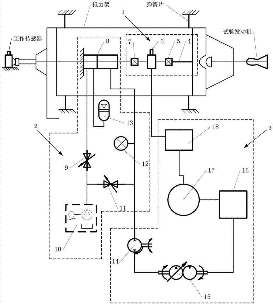
[0027] The present invention is an in-situ calibration system for a thrust bench, such as figure 1 As shown, it includes a standard sensor assembly 1, a hydraulic system 2 and a loading and unloading control system 3.

[0028] The standard sensor assembly 1 includes a sensor pull rod 4 , a front universal flexible member 5 , a standard sensor 6 and a rear universal flexible member 7 .

[0029] One end of the standard sensor 6 is connected to one end of the sensor rod 4 through the front universal flexible member 5, the other end of the standard sensor 6 is connected to the hydraulic cylinder 8 through the rear universal flexible member 7, and the other end of the sensor rod 4 is connected to the thrust frame. frame connected.

[0030] The hydraulic cylinder 8 provides the pulling force required for the in-situ calibration of the system. The standard...


PUM


Abstract

The invention discloses a thrust rack in-situ calibration system, which comprises a standard sensor assembly, a hydraulic system and a loading and unloading control system, wherein the standard sensor assembly comprises a sensor pull rod, a front universal flexible element, a standard sensor and a back universal flexible element, the hydraulic system comprises a hydraulic cylinder, a press cavity oil filling valve, a hand lifting pump, a pulling cavity oil filling valve, an electric joint pressure meter and a pressure cavity energy accumulator, the loading and unloading control system comprises a self control pump, a wide frequency servo motor, a pulse automatic tracking system, a computer and a collecting card, the in-situ thrust calibration system controls the work of the self control pump through the pulse automatic tracking system and the wide frequency servo motor, in addition, measurement signals of the standard sensor are fed back to the computer, the computer transmits the pulse signals to the pulse automatic tracking system through software operation, the automatic loading and unloading on the standard sensor by the hydraulic cylinder is realized, in addition, the necessary time can be stabilized, the loading stability can reach 0.004 percent F.S per 30 minutes (or longer time).

Description

technical field [0001] The invention relates to an in-situ calibration system of a thrust bench, which belongs to the technical field of aerospace engine testing. Background technique [0002] During the test run of the rocket engine, the basic method of thrust measurement is to fix the engine on the moving frame of the thrust frame, and the moving frame and the fixed frame of the thrust frame are connected by spring plates. During the test run, the thrust generated by the engine makes the moving frame and the engine They move together in the thrust direction and act on the load cell through the force transmission mechanism. The thrust frame mainly consists of three parts, one is the thrust transmission mechanism, which is composed of a fixed frame, a moving frame, a spring leaf and pre-tightening force components, etc.; the other is a measuring device, including a working force sensor, a transmission cable, and a data acquisition device; the third is On-site calibration de...

Claims


Application Information

Patent Timeline
IPC IPC(8): G01L25/00G01M15/02
Inventor 覃粒子张晓源常桁王一白刘宇
Owner BEIHANG UNIV
Why Eureka
Try Eureka