Satellite travelling-wave tube thermovacuum testing system

A thermal vacuum test and traveling wave tube technology, which is applied in the field of simulation test systems, can solve the problems of inability to meet the technical requirements of the test, the surface temperature rises, etc., and achieve the effect of shortening the cooling time and improving the heat exchange efficiency.

Inactive Publication Date: 2012-12-12
BEIJING HEFENGTIANCHENG TECH
View PDF4 Cites 12 Cited by
  • Summary
  • Abstract
  • Description
  • Claims
  • Application Information

AI Technical Summary

Problems solved by technology

[0002] The satellite traveling wave tube is one of the important components in the satellite star. The thermal vacuum test is carried out on it, mainly to simulate the vacuum of space, cold darkness and the environment of solar radiation. The existing simulation test system mainly consists of a vacuum container, a heat sink , vacuum pumping, refrigerant supply, infrared heat flow, equipment measurement and control and other sub-systems, the vacuum container is the main body of the system, and the high vacuum pumping unit can make it better than 1.3×10 -3 The vacuum degree of Pa, the heat sink placed in the vacuum container is an important part of the vacuum test system of the thermal component. After the low-temperature refrigerant is used, the temperature of the entire heat sink is kept below -75°C to simulate the cold and dark space environment where the internal components of the satellite are located; the infrared heat flow heating device is installed between the heat sink and the test piece to simulate the sun’s impact on the satellite. The irradiated heat flow of the components can increase the surface temperature of the specimen to 120°C; during the thermal vacuum simulation test, the environmental vacuum of the heat sink and the satellite traveling wave tube is generally better than 1.3×10 -3 Pa, therefore, heat is exchanged between them in the form of heat radiation. The test proves that even if the existing simulation test device changes the -75°C refrigerant into the heat sink into liquid nitrogen (-196°C), the heating power cannot be reduced. The 70W traveling wave tube dropped from the +70°C high temperature heat soak zone to the -35°C low temperature heat soak zone in less than 4 hours, which could not meet the test technical requirements of less than 4 hours for cooling

Method used


Image

  • Satellite travelling-wave tube thermovacuum testing system
  • Satellite travelling-wave tube thermovacuum testing system
  • Satellite travelling-wave tube thermovacuum testing system

Examples


Embodiment Construction

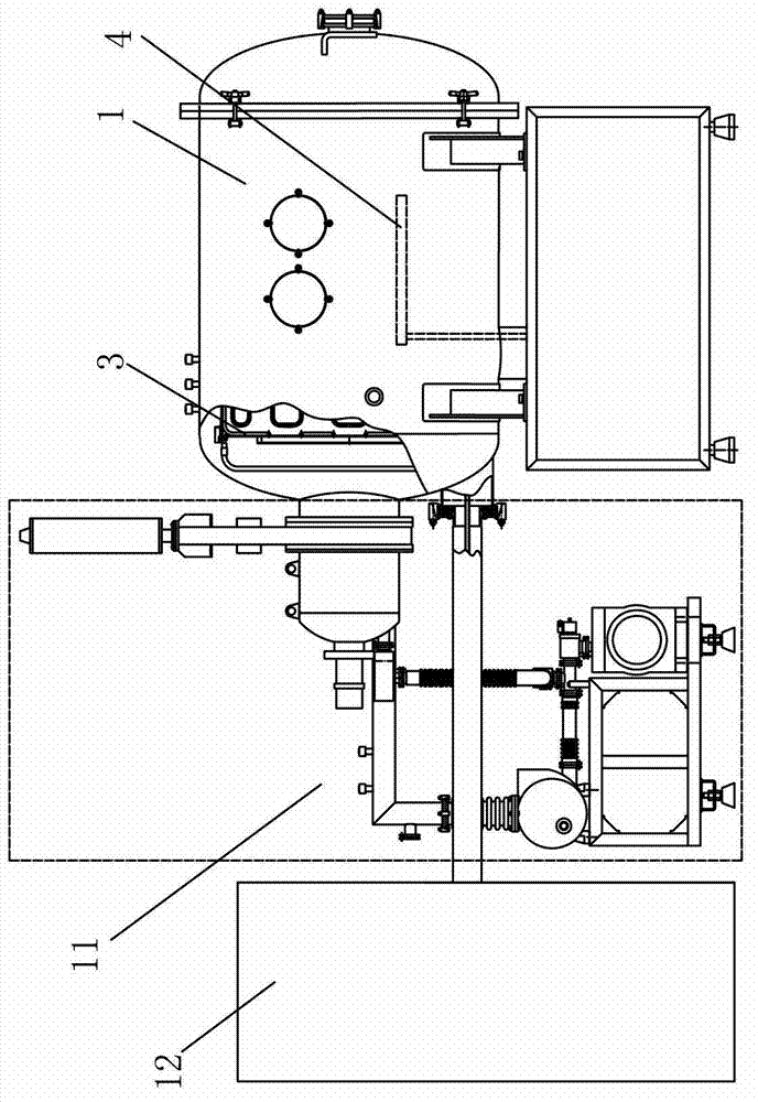
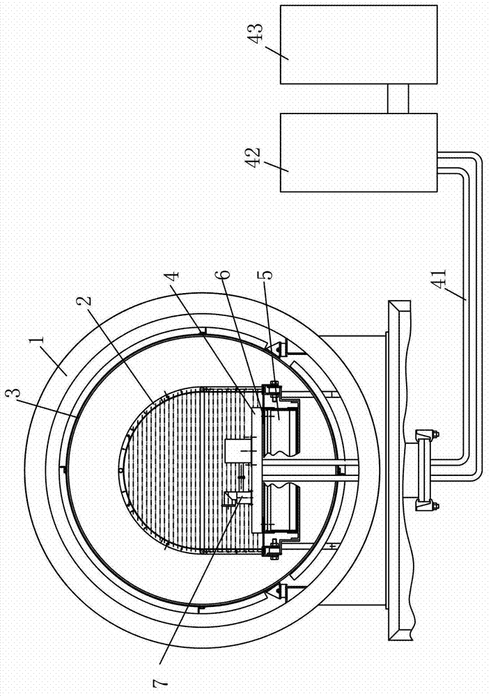
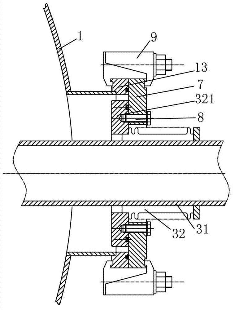
[0020] Such as figure 1 As shown, the satellite traveling wave tube thermal vacuum test system of the present invention includes a vacuum container 1, and the vacuum container 1 is connected with a vacuum pumping unit 11 and a vacuum pumping control system 12, such as figure 2 As shown, the vacuum vessel 1 is provided with an infrared heating device 2, a heat sink 3 is provided between the infrared heating device 2 and the vacuum vessel 1, a traveling wave tube platform 4 is provided inside the infrared heating device 2, and a traveling wave tube platform 4 is provided There are fixing holes, the traveling wave tube platform 4 is fixed on the lifting mechanism 5, and a heat insulating pad 6 is arranged between the traveling wave tube platform 4 and the lifting mechanism 5, the heat insulating pad 6 is made of polytetrafluoroethylene, and the traveling wave tube The tube platform 4 is a hollow cavity structure, in which there are heat exchange tubes in the cavity, and the heat...


PUM


Abstract

The invention provides a satellite travelling-wave tube thermovacuum testing system which comprises a vacuum vessel, wherein the vacuum vessel is internally provided with a travelling-wave tube platform which is fixedly arranged on an elevating mechanism; the travelling-wave tube platform is of a hollow cavity structure; the cavity is internally provided with a heat exchange tube; the heat exchange tube is connected with a refrigerating unit through a coolant pipeline; and the refrigerating unit is positioned outside the vacuum vessel. According to the satellite travelling-wave tube thermovacuum testing system provided by the invention, a travelling-wave tube exchanges heat with the travelling-wave tube platform through a heat conduction mode, so that the heat exchange efficiency between the travelling-wave tube platform and a test piece is greatly improved, The travelling-wave tube cooling time is reduced, and one technical problem in a satellite travelling-wave tube thermovacuum testing process is solved.

Description

technical field [0001] The invention relates to a simulation test system, in particular to a satellite traveling wave tube thermal vacuum test system. Background technique [0002] The satellite traveling wave tube is one of the important components in the satellite star. The thermal vacuum test is carried out on it, mainly to simulate the vacuum of space, cold darkness and the environment of solar radiation. The existing simulation test system mainly consists of a vacuum container, a heat sink , vacuum pumping, refrigerant supply, infrared heat flow, equipment measurement and control and other sub-systems, the vacuum container is the main body of the system, and the high vacuum pumping unit can make it better than 1.3×10 -3 The vacuum degree of Pa, the heat sink placed in the vacuum container is an important part of the vacuum test system of the thermal component. After the low-temperature refrigerant is used, the temperature of the entire heat sink is kept below -75°C to ...

Claims


Application Information

Patent Timeline
Patent Type & Authority Applications(China)
IPC IPC(8): G01R31/24
Inventor 程广河
Owner BEIJING HEFENGTIANCHENG TECH
Why Eureka
Try Eureka