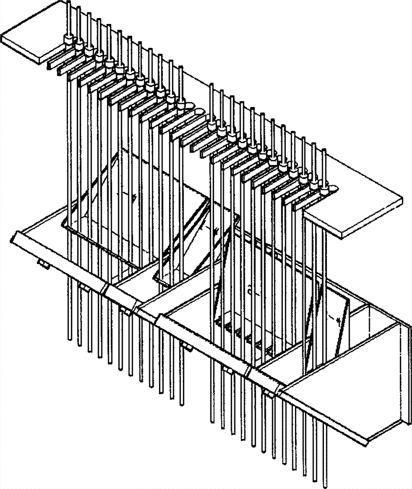
A varnishing device specially used for producing enameled wire by mould method
A painting device and enameled wire technology, which is applied in the direction of conductor/cable insulation, etc., can solve the problems of no paint stop function for single line, increase the labor intensity of operators, reduce production efficiency, etc., and achieve the goal of increasing paint stop for single line Function, reduce reasonable process consumption, and convenient operation
- Summary
- Abstract
- Description
- Claims
- Application Information
AI Technical Summary
Problems solved by technology
Method used
Image
Examples
Embodiment 1
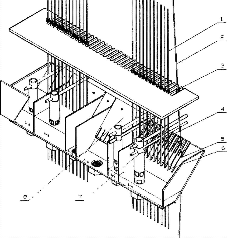
[0031] Example 1: figure 2A schematic diagram of the structural system of a painting device specially used in the production of enameled wires by the mold method of the present invention, which is composed of a mold, a mold frame and a double-groove integral paint vat, and the paint vat shown in the figure can supply 3 heads (the number of more heads can be in the middle) Insert) Normal production of double-insulated enameled wire, 9+3 coats for each head, 9 coats for the inner layer, 3 coats for the outer layer, the 1-inner and 1-outer paint liquids of the first paint pot are at the low level to be produced Paint position, the 2-inner and 2-outer of the second paint vat are in the state of no paint liquid, and the 3-inner and 3-outer paint liquids of the third paint vat are in the paint position of normal production. The preset position of the paint liquid is determined by the outer pipe 7 of the overflow paint flow pipe. The tail of the outer pipe 7 of the overflow paint fl...
Embodiment 2
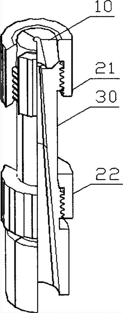
[0034] Example 2: image 3 The structure schematic diagram of the combined enameled wire mold that can be completely disassembled in the production site of the present invention, the combined mold is composed of a mold core 10 that can be disassembled into two halves and a mold cover 30 that can be disassembled into two halves, and also has an opening (also can Not opening) the upper lock mother 21 and the lower lock mother 22 are formed. The mold core 10 or the mold sleeve 30 which can be disassembled into two halves are put together to form a whole mold core and mold sleeve respectively. The required size of the produced wire is determined. There are threads in the middle and lower parts of the mold sleeve, and the top of the thread is a tapered surface. The cone surface and the thread of the mold sleeve are respectively matched with the cone surface and the thread of the inner surface of the lower lock nut. The top surface of the mold sleeve also has a large upper and a lo...
Embodiment 3
[0037] Example 3: Figure 4 A structural schematic diagram of a combined enameled wire mold with a detachable mold core at the production site of the present invention. The combined mold includes: a detachable mold core 10 at the production site, an integral lock nut 20 , and a mold sleeve 30 . The mold cover 30 is composed of two cylindrical bodies, the upper one is thinner and the lower one is thick. The outer surface of the top of the thin cylinder is threaded, and the top surface of the thin cylinder has an inverted cone with a large outside and a small inside. The production site can be disassembled into two halves of the mold core, the joint part is a polished surface, the outer surface is two conical surfaces with opposite tapers, the upper conical surface matches the inner surface of the lock nut 20, and the lower one is inverted The tapered surface matches the inverted tapered surface of the top surface of the mold sleeve 30; the side of the lock nut 20 has an opening...
PUM
 Abstract
Description
Claims
Application Information
 - R&D
- Intellectual Property
- Life Sciences
- Materials
- Tech Scout
- Unparalleled Data Quality
- Higher Quality Content
- 60% Fewer Hallucinations
Browse by: Latest US Patents, China's latest patents, Technical Efficacy Thesaurus, Application Domain, Technology Topic, Popular Technical Reports.
© 2025 PatSnap. All rights reserved.Legal|Privacy policy|Modern Slavery Act Transparency Statement|Sitemap|About US| Contact US: help@patsnap.com


