Sample rod for transmission electron microscope added with magnetic field

A technology of electron microscope and sample rod, which is applied in the direction of circuits, discharge tubes, electrical components, etc., and can solve problems such as electron beam deflection

Active Publication Date: 2015-02-04
INST OF PHYSICS - CHINESE ACAD OF SCI
View PDF3 Cites 0 Cited by
  • Summary
  • Abstract
  • Description
  • Claims
  • Application Information

AI Technical Summary

Problems solved by technology

The sample rod can solve the problem of electron beam deflection, and can load current for a long time to generate a continuous magnetic field

Method used


Image

  • Sample rod for transmission electron microscope added with magnetic field
  • Sample rod for transmission electron microscope added with magnetic field
  • Sample rod for transmission electron microscope added with magnetic field

Examples


Embodiment Construction

[0030] The content of the present invention will be described in detail below with reference to the drawings and embodiments.

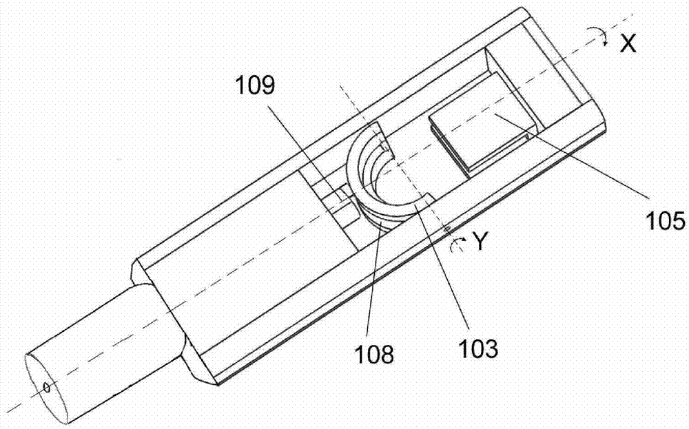
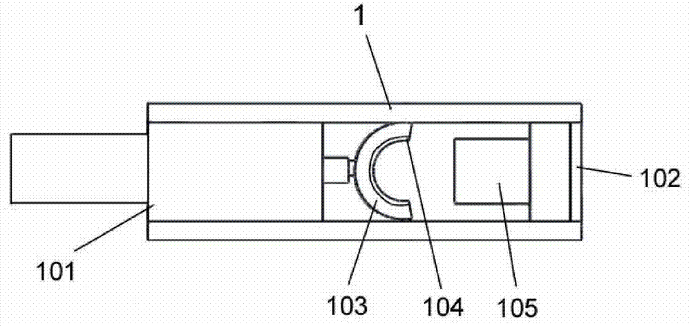
[0031] Such as figure 1 with figure 2 As shown, the transmission electron microscope sample rod of the present invention includes a shaft portion and a head frame 1. The sample is carried in the head frame 1. The incident electron beam is directed toward the sample from a direction substantially perpendicular to the plane where the head frame 1 is located. And can penetrate through the head frame 1. The head frame 1 has a first end 101 and a second end 102 along the length of the sample rod. A carrier 103 is provided in the head frame 1 near the first end 101 of the head frame. The carrier 103 is used to carry the sample 7 and is provided with a channel for the incident electron beam to pass through. A first magnetic coil (not shown in the figure) is provided in the head frame 1 near the second end 102 of the head frame, which can generate a first mag...


PUM


Abstract

The invention discloses a sample rod for a transmission electron microscope added with a magnetic field. The sample rod comprises a head frame, a carrier, a first magnetic coil and a second magnetic coil, wherein the head frame is provided with a first end part and a second end part along the length extending direction of the sample rod; the carrier is used for carrying a sample and is provided with a channel; an incident electron beam can pass through the channel; the carrier is arranged in the head frame and is close to the first end part of the head frame; the first magnetic coil is arranged in the head frame and is close to the second end part of the head frame; when the current is generated, a first magnetic field is generated by the first magnetic coil; the first magnetic field has a magnetizing effect on the sample; the second magnetic coil is arranged in the head frame and is close to the second end part of the head frame; the second magnetic coil is located under the first magnetic coil; when the current is generated, a second magnetic field is generated by the second magnetic coil; and under the action of the second magnetic field, the electron beam which deflects under the action of the first magnetic field deflects toward an incident direction. The sample rod provided by the invention can be used for researching the change in a magnetic domain of a magnetic material under the action of an externally added magnetic field.

Description

Technical field [0001] The invention relates to a transmission electron microscope accessory, more specifically, to a transmission electron microscope sample rod capable of applying a magnetic field. Background technique [0002] With the advancement of technology and the increasing demand of materials science research, in-situ electron microscopy research has become one of the main directions of the development of electron microscopy, and a large number of research results have emerged in recent years. The major electron microscope manufacturers have launched their own sample rods for in-situ research. The strong research demand even gave birth to high-tech companies specializing in the production of various in-situ sample rods (such as the famous Nanofactory Corp.). At present, most of the in-situ sample rods that can be purchased through the market are micro-manipulation, variable temperature zone, electric field (including electrical signal measurement), and force (measuremen...

Claims


Application Information

Patent Timeline
Patent Type & Authority Patents(China)
IPC IPC(8): H01J37/20H01J37/26
Inventor 杨新安姚湲段晓峰田焕芳
Owner INST OF PHYSICS - CHINESE ACAD OF SCI
Why Eureka
Try Eureka