cmos image sensor

A technology of image sensor and photosensitive device, which is applied in the direction of image communication, TV, color TV parts, etc. It can solve the problems of system power consumption, small contrast of captured images, and low signal-to-noise ratio, so as to improve dynamic range and ensure Capture image quality effects

Active Publication Date: 2016-01-20
SHANGHAI ADVANCED RES INST CHINESE ACADEMY OF SCI
View PDF4 Cites 0 Cited by
  • Summary
  • Abstract
  • Description
  • Claims
  • Application Information

AI Technical Summary

Problems solved by technology

However, the existing multiple-exposure method has the following disadvantages: on the one hand, because multiple exposures (integration) are involved, the period for obtaining high dynamic range images is greatly lengthened, and it is not suitable for moving object images. Acquisition; on the other hand, due to the acquisition of multiple images, the back end of the image sensor needs a large amount of storage space for image storage for image processing, and a large number of read and write operations seriously affects the power consumption of the entire system
However, since this non-integrating pixel unit changes the connection mode of the transistors in the original pixel readout circuit, the quality of the captured image of the CMOS image sensor is reduced, and the contrast of the generally shown captured image is small and the signal-to-noise ratio is low.

Method used


Image

  • cmos image sensor
  • cmos image sensor
  • cmos image sensor

Examples


Embodiment Construction

[0047] The implementation of the present invention will be illustrated by specific specific examples below, and those skilled in the art can easily understand other advantages and effects of the present invention from the contents disclosed in this specification.

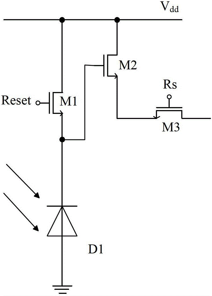
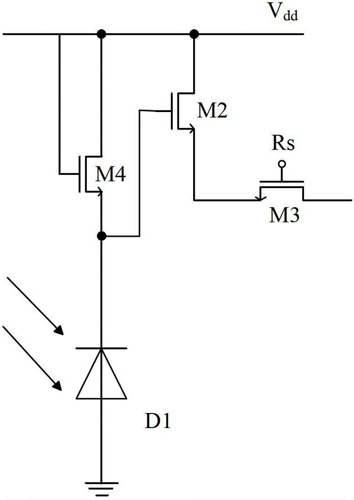
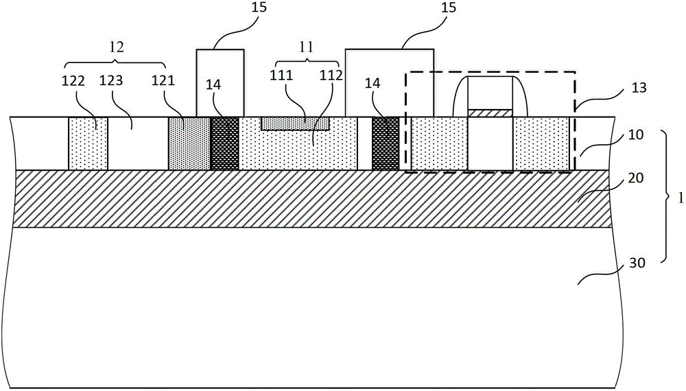
[0048] see Figure 1 to Figure 5 . It should be noted that the structures, proportions, sizes, etc. shown in the drawings attached to this specification are only used to match the content disclosed in the specification, for those who are familiar with this technology to understand and read, and are not used to limit the implementation of the present invention. Limiting conditions, so there is no technical substantive meaning, any modification of structure, change of proportional relationship or adjustment of size, without affecting the effect and purpose of the present invention, should still fall within the scope of the present invention. The disclosed technical content must be within the scope covered. At the sa...


PUM


Abstract

The invention provides a complementary metal oxide semiconductor (CMOS) imaging sensor which at least comprises a semiconductor substrate and a plurality of pixel units located in the semiconductor substrate. Each pixel unit at least comprises a first sensitization device, a second sensitization device, a pixel reading circuit and an isolation structure. Compared with the existing CMOS imaging sensor, the second sensitization devices are added in the traditional CMOS imaging sensor, so that an output response curve of the sensitization devices is nonlinearity, corresponding to the same output voltage swing, maximum magnitudes of the CMOS imaging sensor to sense light are increased, namely a maximum value of lighting levels is increased, and accordingly a dynamic range of the imaging sensor is improved. Simultaneously, a connection mode of the pixel reading circuits of the existing CMOS imaging sensor is kept to guarantee image capture quality of the CMOS imaging sensor.

Description

technical field [0001] The invention belongs to the technical field of semiconductors, relates to a CMOS image sensor, in particular to a CMOS image sensor with improved dynamic range. Background technique [0002] As we all know, an image sensor is a semiconductor device that converts an optical image into an electrical signal. Image sensors can be roughly classified into charge coupled device (CCD) and complementary metal oxide semiconductor (CMOS) image sensors. [0003] CMOS image sensors are generally composed of photosensitive devices and CMOS signal processing circuits (including pixel readout circuits). The current common CMOS image sensor is an active pixel image sensor (APS), which is mainly divided into three types according to the number of transistors it includes: including a reset transistor (ResetTransistor, RST), a source follower transistor (SourceFollowerTransistor, SF) and a row selection transistor ( RowSelect, RS) three-tube CMOS image sensor (3T type)...

Claims


Application Information

Patent Timeline
Patent Type & Authority Patents(China)
IPC IPC(8): H01L27/146H04N5/374
Inventor 田犁汪辉陈杰方娜苗田乐
Owner SHANGHAI ADVANCED RES INST CHINESE ACADEMY OF SCI
Why Eureka
Try Eureka