
Power supply apparatus for vehicle

A technology for power supply devices and vehicles, which is applied to electric power devices, power devices, vehicle components, etc., can solve the problems of reducing cooling performance and hindering the smooth flow of cooling air, and achieve the effect of ensuring cooling performance.

Active Publication Date: 2015-04-01
HONDA MOTOR CO LTD
View PDF7 Cites 0 Cited by
  • Summary
  • Abstract
  • Description
  • Claims
  • Application Information

AI Technical Summary

Problems solved by technology

[0006] In the invention described in the aforementioned Patent Document 1, it is considered that the cooling fins provided on the lower surface of the radiator parallel to the flow direction of the cooling air and the fins provided on the upper surface of the partition wall in a direction perpendicular to the flow direction of the cooling air The ribs function as the above-mentioned reinforcing protrusions, but the ribs block the flow of the cooling air and protrude into the cooling passage, so the smooth flow of the cooling air is hindered by the ribs, resulting in a problem that the cooling performance is reduced.
When the direction of the rib is made parallel to the flow direction of the cooling air in order to avoid the above, the direction of the cooling fins of the radiator is the same as the direction of the rib, so there is a possibility that the rigidity can only be improved for a bending load in a specific direction. problem of effect

Method used


Image

  • Power supply apparatus for vehicle
  • Power supply apparatus for vehicle
  • Power supply apparatus for vehicle

Examples


Embodiment Construction

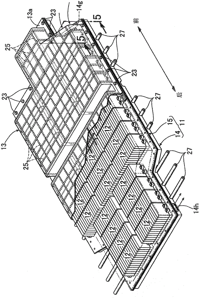
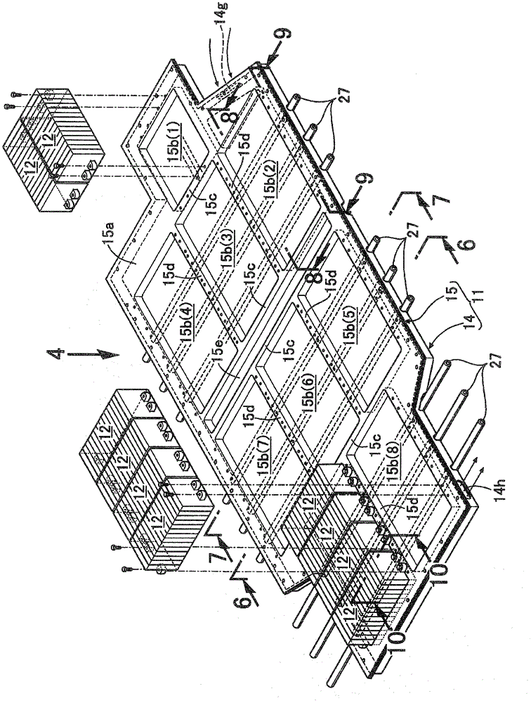
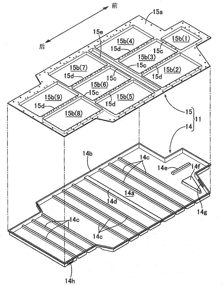
[0047] Below, based on Figure 1 to Figure 10 A first embodiment of the present invention will be described.

[0048] Such as figure 1 As shown, a power supply device for a vehicle that supplies power to a motor generator, which is a drive source for driving an electric vehicle, mounts a plurality (34 in this embodiment) of battery modules 12 on the upper surface of a support plate 11 mounted on the vehicle body. And it is comprised by the battery cover 13 covering the upper part.

[0049] Such as image 3 As shown, the support plate 11 formed elongatedly along the front-rear direction of the vehicle body is formed by overlapping the lower lower plate 14 and the upper upper plate 15, and joining the peripheral parts of the lower plate and the upper plate by spot welding, wherein , the lower plate 1 is formed by pressing an aluminum plate, and the upper plate 15 is formed by pressing an aluminum plate.

[0050] The lower plate 14 is a saucer-shaped member, and has a flange ...


PUM


Abstract

A power supply apparatus includes a plurality of battery modules, a support plate, a plurality of first reinforcing projections, and a plurality of second reinforcing projections. The support plate supports the battery modules and includes a first plate and a second plate. The first plate thermally contacts bottom surfaces of the battery modules. The second plate is placed on a bottom surface of the first plate to define cooling spaces between the first and second plates. A coolant is to flow in the cooling spaces. The plurality of first reinforcing projections is provided on at least one of the first and second plates. The first reinforcing projections project into the cooling spaces and extend in a first direction. The plurality of second reinforcing projections is provided on a top surface of the first plate and extending in a second direction intersecting with the first direction.

Description

technical field [0001] The present invention relates to a power supply device for a vehicle, wherein a support plate for supporting a plurality of battery modules constituted by an aggregate of a plurality of battery cells includes a first plate and a second plate, the first plate and the battery module The bottom surface of the second plate is in thermal contact with the bottom surface of the first plate, and the lower surface of the second plate and the first plate are overlapped to define a cooling space for cooling medium to flow between the second plate and the first plate. Background technique [0002] Patent Document 1 below discloses a technology in which a support plate supporting a battery pack member includes a heat sink that is in thermal contact with the lower surface of the battery pack member, and a partition wall that is bonded to the lower side of the heat sink. A cooling passage through which cooling air flows is defined between the heat sink and the heat s...

Claims


Application Information

Patent Timeline
Patent Type & Authority Patents(China)
IPC IPC(8): H01M2/10H01M10/6554H01M10/6556H01M10/6563B60K1/04B60L11/18H01M10/60H01M10/613H01M10/617H01M10/625H01M10/647H01M10/6566H01M50/209H01M50/224H01M50/262H01M50/264H01M50/276
CPCH01M10/5032H01M2/1077H01M10/5057H01M10/5067H01M10/5016H01M10/5063H01M2/1083H01M10/5053H01M10/625H01M10/6563H01M10/647H01M10/6556H01M10/6554H01M10/6561Y02E60/10H01M50/209H01M50/224H01M50/276H01M50/262H01M50/264
Inventor 藤原秀智樱井敦因和久
Owner HONDA MOTOR CO LTD
Learn More