Eureka AIR delivers breakthrough ideas for toughest innovation challenges, trusted by R&D personnel around the world.

Front underfloor structure of vehicle

A vehicle and floor technology, applied to vehicle parts, upper structure, upper structure sub-assembly, etc., can solve problems such as improvement of aerodynamic performance, decrease of lift coefficient, increase of air resistance coefficient, etc.

Inactive Publication Date: 2012-12-12
NISSAN MOTOR CO LTD
View PDF9 Cites 26 Cited by
  • Summary
  • Abstract
  • Description
  • Claims
  • Application Information

AI Technical Summary

Problems solved by technology

[0005] However, the underfloor structure of the front part of the conventional vehicle is a structure in which a chin spoiler that lowers the lift coefficient is provided at the position of the front end of the vehicle.
Therefore, for the running wind flowing under the front floor, the chin spoiler acts as a resistance protrusion that hinders the smooth flow of the running wind and increases the air resistance coefficient, and there is a problem that the desired improvement in aerodynamic performance cannot be expected.

Method used


Image

  • Front underfloor structure of vehicle
  • Front underfloor structure of vehicle
  • Front underfloor structure of vehicle

Examples


Embodiment 1

[0055] First, the configuration will be described.

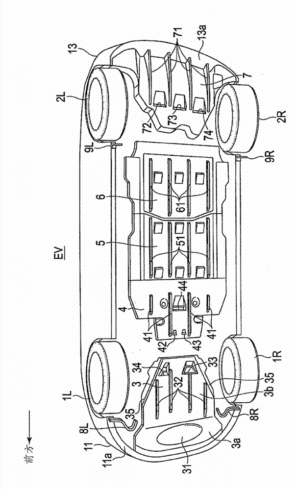
[0056] figure 1 It is a perspective view showing the entire underfloor structure of an electric vehicle (an example of a vehicle) to which the front underfloor structure of the first embodiment is applied. Below, based on figure 1 The overall underfloor structure will be described.

[0057] Such as figure 1 As shown, the overall underfloor structure of the electric vehicle EV in Embodiment 1 includes: a pair of left and right front wheels 1L, 1R, a pair of left and right rear wheels 2L, 2R, a front lower cover 3, and a motor room rear lower cover 4 , the first battery lower cover plate 5, the second battery lower cover plate 6, the rear lower cover plate 7, the left and right pair of front deflectors 8L, 8R, the left and right pair of rear deflectors 9L, 9R.

[0058] The left and right pair of front wheels 1L, 1R are steering wheels and driving wheels, and are connected via front suspension links 10L, 10R (refer to fig...


PUM


Abstract

A front underfloor structure of a vehicle (EV) is provided with a protruding member, which protrudes below the front underfloor surface of the vehicle, and redirects the flow of air that flows around the front underfloor while traveling. The protruding member is configured as a protruding member with curved surface (31), which is positioned further forward on the vehicle than the front tires (1L, 1R), and is disposed in the center of the front underfloor and straddles the vehicle center line (CL). The circumference of the protrusion of the protruding member with curved surface (31) is longest in the vehicle longitudinal direction at the position of the vehicle center line (CL), and the circumference of the protrusion in the vehicle longitudinal direction becomes gradually shorter in with increasing distance from the vehicle center line (CL) on both sides in the vehicle width direction.

Description

technical field [0001] The present invention relates to a front underfloor structure of a vehicle that rectifies the flow of traveling wind flowing around the underfloor through a protruding member. Background technique [0002] Conventionally, as a front underfloor structure of a vehicle that rectifies the flow of running wind flowing around the underfloor front, it is known to provide a chin as a protruding member at the position where the front bumper fascia is set at the front end of the vehicle. Spoiler (for example, refer to Patent Document 1). [0003] In this conventional underfloor structure of a vehicle, the aim is to limit the amount of running wind flowing into the underfloor of the vehicle by providing a chin spoiler, and to generate wind in the front of the vehicle body that floats up as the vehicle speed increases. Downward force (descent force) that suppresses upward movement. [0004] Patent Document 1: (Japanese) Unexamined Patent Publication No. 2006-327...

Claims


Application Information

Patent Timeline
Patent Type & Authority Applications(China)
IPC IPC(8): B62D35/02B62D25/20B62D37/02
CPCB62D35/02Y02T10/88Y02T10/82
Inventor 垣内武阿高雅弘小川洋平中岛一昭石原裕二
Owner NISSAN MOTOR CO LTD
Why Eureka
Eureka Blog
Learn More