
Method of operating a metering pump and apparatus having a metering pump

A technology for metering pumps and equipment, which is applied in the direction of mechanical equipment, pumps, pump control, etc., and can solve problems such as changes in the operating environment

Active Publication Date: 2016-01-13
WEBASTO AG
View PDF9 Cites 0 Cited by
  • Summary
  • Abstract
  • Description
  • Claims
  • Application Information

AI Technical Summary

Problems solved by technology

Operating environment may change over time

Method used


Image

  • Method of operating a metering pump and apparatus having a metering pump
  • Method of operating a metering pump and apparatus having a metering pump
  • Method of operating a metering pump and apparatus having a metering pump

Examples


Embodiment Construction

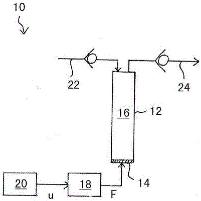
[0034]FIG. 1 schematically shows an example of a device 10 for pumping a liquid, for example fuel, from an inlet line 22 to an outlet line 24 by means of a metering pump 12 . The metering pump 12 includes a housing and a piston 14 defining a pump chamber 16 together with the housing. The current position of the piston 14 relative to the housing defines the current volume of the pump chamber 16 . FIG. 1 shows the piston 14 in an initial position in which the pump chamber 16 assumes its maximum volume.

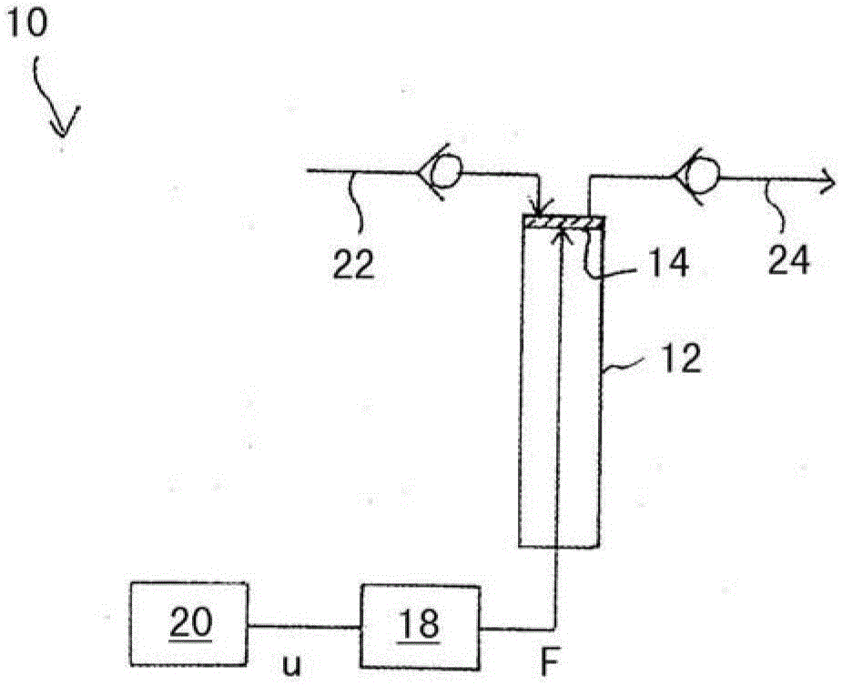
[0035] FIG. 2 shows the piston 14 in the end position in which the volume of the pump chamber 16 is zero. The piston 14 is connected to an electric drive unit 18 . The drive unit 18 is adapted to cyclically or periodically apply a force F to the piston 14 to move the piston 14 back and forth between its starting position and its end position. The metering pump 12 can have a spring (not shown) which returns the piston 14 from the end position to the start position without the ...


PUM


Abstract

The invention relates to a method of operating a metering pump (12), in particular for delivering fuel to a vehicle heater, wherein the metering pump comprises a piston (14) movable back and forth between a start position and an end position, and capable of By applying a voltage to the driven drive unit (18), the method has the following measures: controlling and / or regulating the voltage to generate an effective voltage for moving the piston from a start position to an end position, wherein the effective voltage is at the start position The first maximum value (U1) is reached in the initial phase (t0-t1) and falls below the first maximum value in the subsequent intermediate phase (t1-t2). According to the invention, the effective voltage reaches a second maximum value (U3) in the end phase (t2-t3) immediately following the intermediate phase. During the initial phase and / or the intermediate phase and / or the final phase, the effective voltage can be constant or defined, for example, by a step function. The invention also relates to a device with a metering pump (12) and a control / regulation unit (20), wherein the control / regulation unit (20) is adapted to control the voltage applied to the drive unit (18) of the metering pump.

Description

technical field [0001] The invention relates to a method of operating a metering pump, in particular for delivering fuel to a vehicle heating unit, wherein the metering pump comprises a piston movable back and forth between a start position and an end position for delivery, With an electrically excited drive unit, the method has the following steps: [0002] controlling and / or regulating the voltage to produce an effective voltage for moving the piston from a starting position to an ending position, wherein the effective voltage exhibits a first maximum value in the initial phase and is lower than the first value in the subsequent intermediate phases maximum value, [0003] The invention also relates to a device for carrying out the method. Background technique [0004] A method of this type is known from document DE 10 2005 024 858 A1. The magnitude of the voltage applied to the drive unit determines the magnitude of the drive force acting on the reciprocally movable pis...

Claims


Application Information

Patent Timeline
Patent Type & Authority Patents(China)
IPC IPC(8): F04B49/06
CPCF04B49/06F04B2201/0204F04B2203/0402F04B49/02F04B17/03F04B35/045F04B49/065
Inventor G·高尔特兹
Owner WEBASTO AG
Features
  • Generate Ideas
  • Intellectual Property
  • Life Sciences
  • Materials
  • Tech Scout
  • Unparalleled Data Quality
  • Higher Quality Content
  • 60% Fewer Hallucinations
Learn More