
Aviation Gas Helical Rotary Engine

A jet engine and solenoid technology, applied in engine components, machines/engines, non-variable engines, etc., can solve the problems of not being able to take off in time, occupying space and tonnage of the aircraft carrier, complex structure, etc., and achieve long service life , improve reliability, overcome the effect of overheating

Active Publication Date: 2018-06-05
肇庆高新区伙伴汽车技术有限公司
View PDF7 Cites 0 Cited by
  • Summary
  • Abstract
  • Description
  • Claims
  • Application Information

AI Technical Summary

Problems solved by technology

Regardless of the steam catapult or the electromagnetic catapult, its structure is very complicated, not only takes up a lot of space and tonnage of the aircraft carrier, but also cannot take off in time against time

Method used


Image

  • Aviation Gas Helical Rotary Engine
  • Aviation Gas Helical Rotary Engine
  • Aviation Gas Helical Rotary Engine

Examples


Embodiment Construction

[0060] The specific implementation manners of the present invention will be further described in detail below.

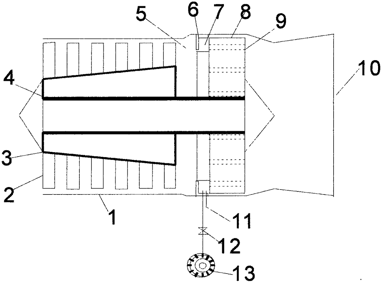
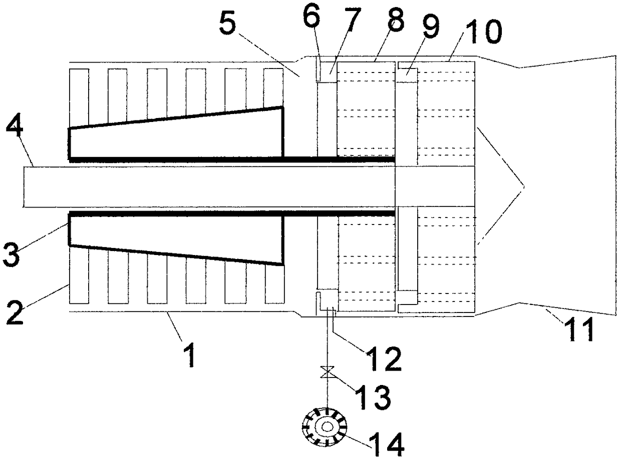
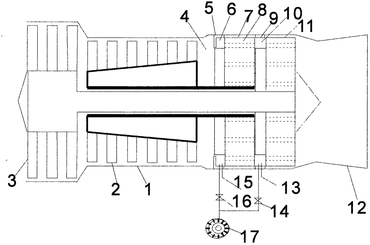
[0061] A gas-fired helical rotor jet engine, including a turbojet engine, uses a stepped helical rotor instead of a turbine, and a diffuser is arranged between the exhaust port of the compressor and the stepped helical rotor, and is fixed on the casing in an L-shaped can The combination of the annular channel for adjusting the air volume and the steps of the spiral tube rotor constitutes the first annular combustion chamber. The annular combustion chamber is equipped with at least one fuel injection device and an ignition device. The damper of the annular channel can control the amount of compressed air entering the first combustion chamber and the amount of compressed air flowing through the annular channel around the spiral tube rotor. This mechanism constitutes a gas generator, and the high-speed flowing air is decelerated by the diffuser during operation. The hi...


PUM


Abstract

The invention discloses five kinds of aircraft gas spiral tube rotor engines including a gas spiral tube rotor jet engine, a spiral tube rotor propeller or shaft engine, a spiral tube rotor fan engine and a spiral tube rotor fan boost engine, wherein the gas spiral tube rotor jet engine is formed through a great improvement on an aircraft gas turbo-jet engine, and the spiral tube rotor propeller or shaft engine, the spiral tube rotor fan engine and the spiral tube rotor fan boost engine are derived from the aircraft gas spiral tube rotor jet engine. The gas spiral tube rotor jet engine is used as the core engine, an integrated spiral tube rotor which is small in unit mass superficial area is used for replacing a blade turbine to convert energy, an annular combustion chamber is used for replacing a thin flame tube to convert chemical energy of fuel into thermal energy, and therefore the gas spiral tube rotor jet engine is long in service life, less in fault, low in manufacturing cost and high in reliability; the spiral tube rotor propeller or shaft engine, the spiral tube rotor fan engine and the spiral tube rotor fan boost engine have the advantages of the core engine and also have the advantage of saving energy; and a shipboard aircraft provided with the spiral tube rotor fan boost engine can smoothly land and take off without a blocking device and a catapult-launching device.

Description

technical field [0001] The invention relates to an aviation gas turbine engine, in particular to an aviation gas helical tube rotor engine which is significantly improved over the four types of aviation gas turbine engines in the prior art. Background technique [0002] Aviation gas turbine engine is referred to as aviation gas engine for short, including turbojet engine, turboprop engine, turboshaft engine and turbofan engine. It is the main power plant of modern fixed-wing aircraft and helicopters. The turbojet engine consisting of a compressor, a combustion chamber and a gas turbine driving the compressor is also called a core engine, because it is used to provide high-pressure, high-temperature gas, so it is also called a gas generator, and the other three types are derived from it. [0003] The short life of aviation gas turbine engines is a worldwide problem. According to the information on aero-engine powerhouses, the Russian AL-31F engine has a nominal life of 1,00...

Claims


Application Information

Patent Timeline
Patent Type & Authority Patents(China)
IPC IPC(8): F01D15/08F01D1/38F01D15/12F01D17/00F23R3/52
CPCF01D1/38F01D15/08F01D15/12F01D17/00F23R3/52
Inventor 罗显平
Owner 肇庆高新区伙伴汽车技术有限公司
Features
  • Generate Ideas
  • Intellectual Property
  • Life Sciences
  • Materials
  • Tech Scout
  • Unparalleled Data Quality
  • Higher Quality Content
  • 60% Fewer Hallucinations
Learn More