Method for producing a heat exchanger and heat exchanger

A heat exchanger and structure technology, applied in the direction of heat exchanger fixing, heat exchange equipment, heat sink, etc., can solve the problems of complex structure type, large weight, etc., and achieve the effect of avoiding forced stress, small structure, and optimizing heat dissipation

Inactive Publication Date: 2012-12-12
BOA BALG UND KOMPENSATOREN TECH
View PDF6 Cites 2 Cited by
  • Summary
  • Abstract
  • Description
  • Claims
  • Application Information

AI Technical Summary

Problems solved by technology

But the structures so far show a structurally complex type of structure, which acquires a large weight

Method used


Image

  • Method for producing a heat exchanger and heat exchanger
  • Method for producing a heat exchanger and heat exchanger
  • Method for producing a heat exchanger and heat exchanger

Examples


Embodiment Construction

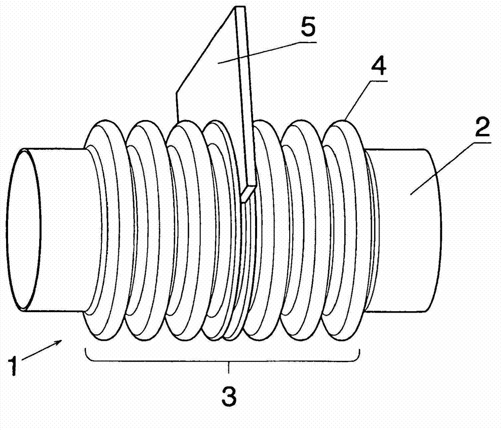
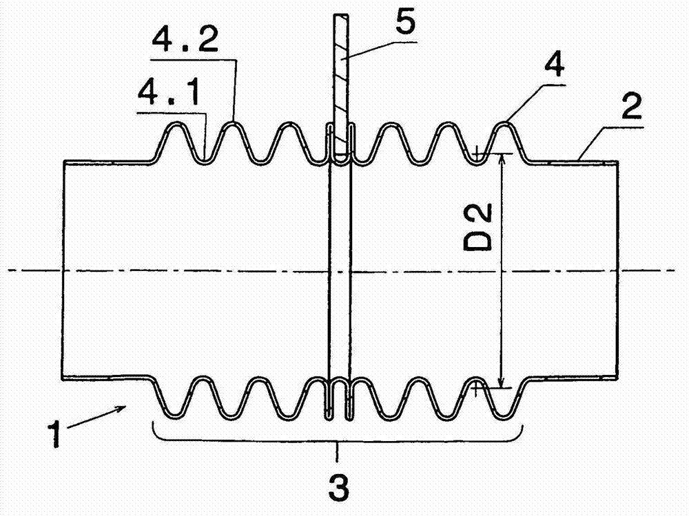
[0016] figure 1 and figure 2 A general view and a side view showing an overview of the heat exchanger 1 according to the invention. The heat exchanger 1 comprises a pipe 2 with bellows 3 . The pipe 2 and the corrugated body 3 are here preferably made of stainless steel and produced in one piece. The corrugated body 3 has corrugations 4 with troughs 4.1 and crests 4.2. The sheet metal 5 is pressed between two corrugations 4 . shown here figure 1 In the exemplary embodiment shown by way of example, a single sheet metal 5 clamped between the corrugations 4 is shown. It is also possible to insert several sheet metals, wherein the sheet metals can be inserted not only from one side, but also from two opposite sides of the pipe and thus point radially in different directions. This can be applied flexibly depending on the space requirements or cooling requirements.

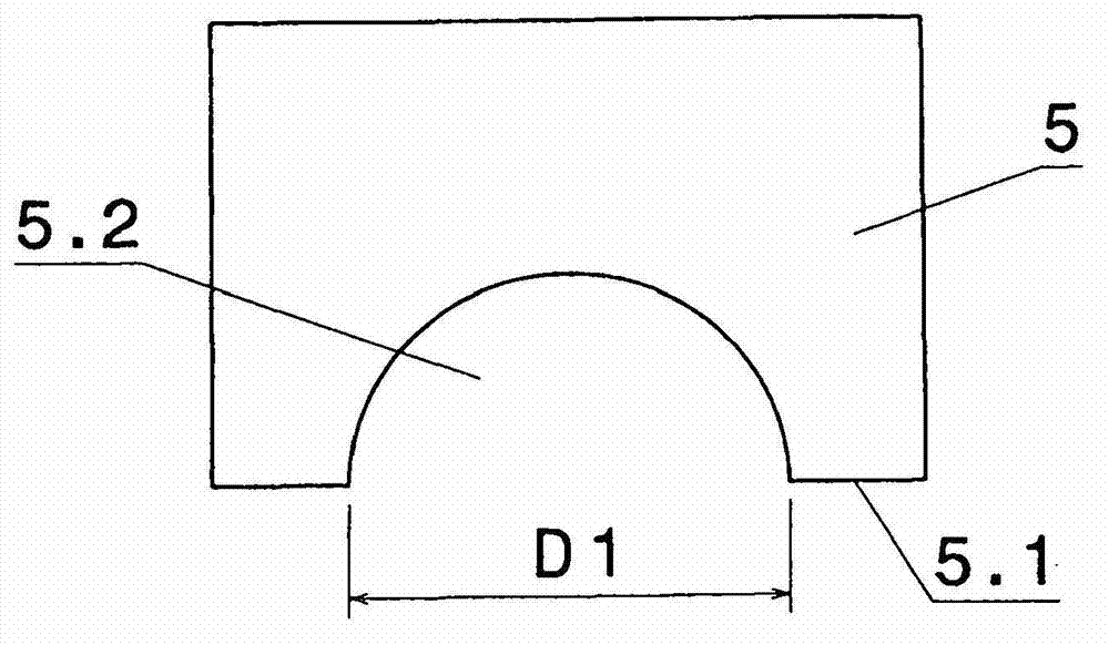
[0017] image 3 Such a sheet 5 is shown. The sheet metal 5 here has a rectangular basic shape, wherein a sem...


PUM


Abstract

The invention relates to a method for producing a heat exchanger. According to said method, at least one plate (5) for dissipating heat is inserted between two neighbouring corrugations (4) of the corrugated body (3) and the corrugations are pressed together in such a way that the inserted plate is clamped in a shape and force closure way between the corrugations. The invention also relates to a heat exchanger of this type for cooling fluids, said exchanger comprising a tube (2) that is partially designed as a corrugated tube and has at least one plate for dissipating heat that is clamped between the two corrugations of the corrugated body.

Description

technical field [0001] The invention relates to a method for producing a heat exchanger for a cooling fluid, comprising a pipe, which is partially configured as a corrugated body, and to a heat exchanger for a cooling fluid, comprising a pipe, the pipe Partially configured as a corrugated body. Background technique [0002] This type of heat exchanger is used to exchange heat between fluids - gases or liquids. A first fluid which is to be cooled or heated flows through the pipe. The pipe is guided in a further container surrounding the pipe, which contains a second fluid, wherein the second fluid flushes the pipe with the first fluid and the two fluids have a temperature difference with respect to each other. Such heat exchangers are used, for example, in systems for exhaust gas recirculation in automobiles, to heat the air supplied to the passenger compartment of an automobile by waste heat from the engine or in similar applications where exhaust air, such as the exhaust ...

Claims


Application Information

Patent Timeline
Patent Type & Authority Applications(China)
IPC IPC(8): F28F1/08F28F1/12F28F1/24
CPCF28F2275/122F28F1/24F28F2275/12F28F1/08F28F1/12F28F2215/12F28F1/30Y10T29/49378
Inventor W·扬策A·邦克U·维尔德
Owner BOA BALG UND KOMPENSATOREN TECH
Why Eureka
Try Eureka