
Transparent piezoelectric sheet with frame containing transparent piezoelectric sheet, touch panel containing transparent piezoelectric sheet, and electronic device

A touch panel and electronic device technology, which is applied to the measurement of properties of piezoelectric devices, electrical digital data processing, and input/output process of data processing, etc., and can solve the problem of inability to detect the strength of the user's pressing.

Inactive Publication Date: 2012-12-12
DAIKIN IND LTD +1
View PDF8 Cites 31 Cited by
  • Summary
  • Abstract
  • Description
  • Claims
  • Application Information

AI Technical Summary

Problems solved by technology

[0003] In the touch panels that have been put into practical use so far, only the position pressed by the user (in this specification, sometimes referred to as a touch position) can be detected, and the intensity of the user's press (that is, the magnitude of the pressing pressure (strength) cannot be detected. )

Method used


Image

  • Transparent piezoelectric sheet with frame containing transparent piezoelectric sheet, touch panel containing transparent piezoelectric sheet, and electronic device
  • Transparent piezoelectric sheet with frame containing transparent piezoelectric sheet, touch panel containing transparent piezoelectric sheet, and electronic device
  • Transparent piezoelectric sheet with frame containing transparent piezoelectric sheet, touch panel containing transparent piezoelectric sheet, and electronic device

Examples


no. 1 Embodiment

[0097]

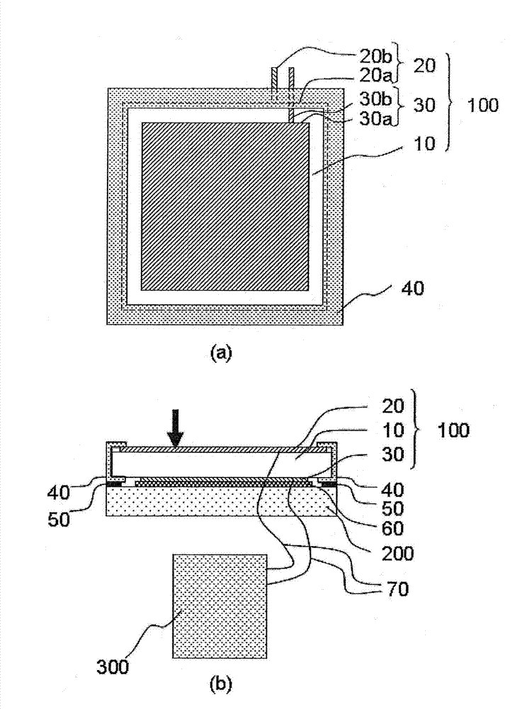
[0098] First, the configuration of the transparent piezoelectric sheet of this embodiment will be described.

[0099] The transparent piezoelectric sheet with a frame of the present embodiment is characterized in that it includes a transparent piezoelectric sheet 100, which includes: a transparent piezoelectric film 10, which contains an organic polymer; a first transparent flat plate electrode 20, which is configured on the first main surface of the transparent piezoelectric film 10; and a second transparent plate electrode 30 configured on the second main surface of the transparent piezoelectric film 10; and the first transparent plate electrode 20 has a first transparent Plate electrode portion 20a, the above-mentioned second transparent plate electrode 30 has a second transparent plate electrode portion 30a, the outline of the above-mentioned second transparent plate electrode portion 30a is located inside the outline of the above-mentioned first transparent plat...

no. 2 Embodiment

[0152]

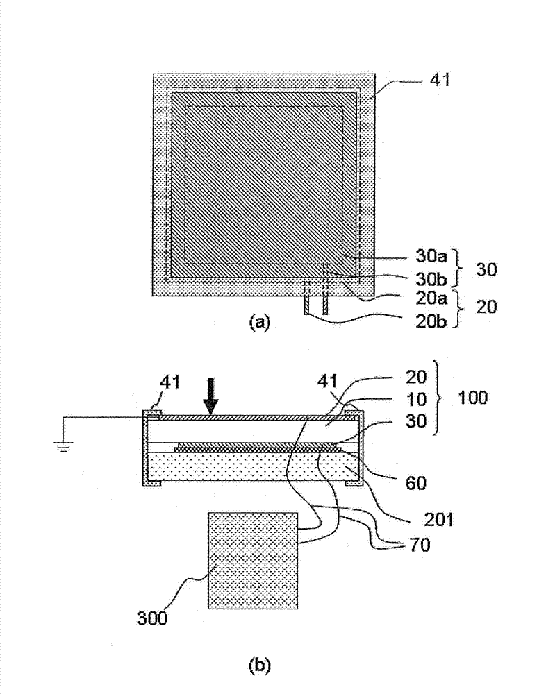
[0153] First, the configuration of the touch panel of this embodiment will be described.

[0154] The touch panel of this embodiment is characterized in that it includes a transparent piezoelectric sheet 100, which includes: a transparent piezoelectric film 10, which contains an organic polymer; a first transparent flat plate electrode 20, which is arranged on the transparent piezoelectric film. The first main surface of the electric thin film 10; and a second transparent flat electrode 30, which is arranged on the second main surface of the transparent piezoelectric thin film 10; and the first transparent flat electrode 20 has a first transparent flat electrode part 20a , the above-mentioned second transparent plate electrode 30 has a second transparent plate electrode portion 30a, the outline of the first transparent plate electrode portion 20a is located inside the outline of the above-mentioned second transparent plate electrode portion 30a when viewed from above...

no. 3 Embodiment

[0166]

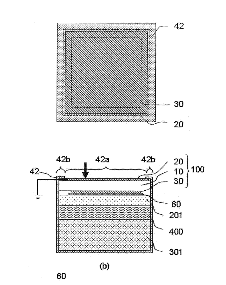
[0167] First, the configuration of the electronic device of this embodiment will be described.

[0168] The electronic equipment of the present embodiment includes a transparent piezoelectric film 100, which includes: a transparent piezoelectric film 10, which contains an organic polymer; a first transparent plate electrode 20, which is arranged on the transparent piezoelectric film 10 The first main surface; and a second transparent flat electrode 30, which is arranged on the second main surface of the transparent piezoelectric film 10; and the first transparent flat electrode 20 has a first transparent flat electrode portion 20a, and the second The transparent plate electrode 30 has a second transparent plate electrode portion 30a, and the outline of the second transparent plate electrode portion 30a is located inside the outline of the first transparent plate electrode portion 20a in plan view; The transparent piezoelectric sheet 100; the above-mentioned frame bo...


PUM

PropertyMeasurementUnit
thicknessaaaaaaaaaa

Abstract

Disclosed is a transparent piezoelectric sheet with a frame, which has a wider effective area, is capable of more accurate touch pressure recognition, and has low manufacturing cost and a pleasing appearance. The piezoelectric sheet with a frame comprises one transparent piezoelectric membrane containing an organic polymer, one first transparent flat-plate electrode disposed to a first principal surface of the transparent piezoelectric membrane, and one second transparent flat-plate electrode disposed to a second principal surface of the transparent piezoelectric membrane. The first transparent flat-plate electrode includes a first transparent flat-plate electrode section, and the second transparent flat-plate electrode includes a second transparent flat-plate electrode section. The outline of the second transparent electrode section includes a transparent piezoelectric sheet, which when seen in plan view is positioned inside the outline of the first transparent flat-plate electrode section, and a frame covering the periphery of the transparent piezoelectric sheet. The outline of the first transparent flat-plate electrode section when seen in plan view overlaps the whole of the frame, and the outline of the second transparent flat-plate electrode section does not overlap the frame at all.

Description

technical field [0001] The invention relates to a transparent piezoelectric sheet with a frame, a touch panel and an electronic device each having a transparent piezoelectric sheet. Background technique [0002] In recent years, display and input devices in which a touch panel as an input device is provided on the front of a display device such as a liquid crystal display have been put into practical use, and are used in mobile devices such as mobile phones and operation panels of home appliances. When a touch panel display and input device is used, the user can intuitively operate the device by pressing a display on the screen. [0003] In the touch panels that have been put into practical use so far, only the position pressed by the user (in this specification, sometimes referred to as a touch position) can be detected, and the intensity of the user's press (that is, the magnitude of the pressing pressure (strength) cannot be detected. ). In this specification, sometimes ...

Claims


Application Information

Patent Timeline
Patent Type & Authority Applications(China)
IPC IPC(8): G06F3/041G01L1/16
CPCG06F3/041G06F2203/04105G01L1/16G06F3/0414
Inventor 小谷哲浩桑岛祐己向井惠吏高明天金村崇表研次大东弘二
Owner DAIKIN IND LTD
Learn More