Hydraulic stirring device

A stirring device and hydraulic technology, applied in the directions of mixer accessories, dissolving, mixers, etc., can solve the problems of difficult cleaning, insufficient stirring, inconvenient operation, etc., to solve the problem of high failure rate, improve the stirring effect, and increase the turbulent state. Effect

Inactive Publication Date: 2012-12-19
辽宁中顺科技装备有限公司
View PDF5 Cites 5 Cited by
  • Summary
  • Abstract
  • Description
  • Claims
  • Application Information

AI Technical Summary

Problems solved by technology

The existing stirring device is generally composed of a cylinder, a stirring impeller installed in the cylinder, and a motor or motor that drives the stirring impeller to rotate. Because of its unreasonable structure, there are defects such as high failure rate, insufficient stirring, inconvenient operation and difficult cleaning. In order to effectively improve the stirring efficiency and stirring effect, it is necessary to improve the structure of the existing stirring device

Method used


Image

  • Hydraulic stirring device

Examples


Embodiment Construction

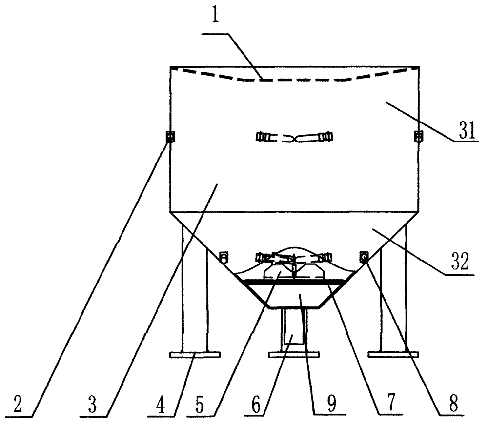
[0017] The present invention will be further described below in conjunction with the accompanying drawings.

[0018] Such as figure 1 As shown, the hydraulic stirring device of the present invention includes a support column 4 and a cylinder 3 arranged on the support column 4. In order to effectively increase the stability of the present invention, the support column 4 can be provided with a plurality of rings located on the Around the barrel 3.

[0019] The upper end of the cylinder body 3 is provided with a feeder 1. In the present invention, the feeder 1 is preferably an inverted V-shaped structure, so that when the pulping material is added to the cylinder body 3, the pulping material can pass through the feeder 1. Sliding into the cylinder body 3 can effectively prevent the pulping material from falling outside the cylinder body 3, so as to effectively improve the utilization rate of the pulping material. The lower end of the cylinder body 3 is provided with a discharge...


PUM


Abstract

The invention relates to the technical field of stirring devices and particularly to a hydraulic stirring device. The stirring device comprises a supporting column and a cylinder arranged on the supporting column. The upper end of the cylinder is provided with a feeder, and the lower end of the cylinder is provided with a discharging pipe; a stirring spray head I is arranged on the inner wall at the upper part of the cylinder, and a nozzle of the stirring spray head I is arranged to be tilted downwardly at an angle of 6 to 10 degrees; a stirring spray head II is arranged on the inner wall at the lower part of the cylinder, and a nozzle of the stirring spray head II is arranged to be tilted upwardly at an angle of 6 to 10 degrees; the stirring spray head I and the stirring spray head II are arranged at opposite directions; and an inert stirring wheel is provided at a central position at the lower part in the cylinder. According to the invention, the device does not need to be driven by an electrical machine or a motor, and the technical problems of a high fault rate, troublesome operation, poor stirring effects and the like in the prior art are effectively overcome.

Description

technical field [0001] The invention relates to the technical field of stirring devices, in particular to a hydraulic stirring device. Background technique [0002] Stirring devices are widely used in industrial and agricultural production and are well known and common. The existing stirring device is generally composed of a cylinder, a stirring impeller installed in the cylinder, and a motor or motor that drives the stirring impeller to rotate. Because of its unreasonable structure, there are defects such as high failure rate, insufficient stirring, inconvenient operation and difficult cleaning. And deficiencies, in order to effectively improve the stirring efficiency and stirring effect, it is necessary to improve the structure of the existing stirring device. Contents of the invention [0003] The object of the present invention is to provide a hydraulic stirring device with simple structure, reasonable design, good stirring effect and low failure rate in view of the d...

Claims


Application Information

Patent Timeline
Patent Type & Authority Applications(China)
IPC IPC(8): B01F13/00B01F15/02
Inventor 张庆营马丛山邱兆珍任瑛吴北平
Owner 辽宁中顺科技装备有限公司
Why Eureka
Try Eureka