A centrifugal fan impeller

A centrifugal fan and impeller technology, applied in the field of power machinery, can solve the problems of increased production cost, poor processing technology, easy falling off of ceramic blocks, etc., to improve energy conversion efficiency, uniform load pressure distribution, and increase impact resistance. effect of corrosion

Active Publication Date: 2019-12-24
JILIN UNIV
View PDF2 Cites 0 Cited by
  • Summary
  • Abstract
  • Description
  • Claims
  • Application Information

AI Technical Summary

Problems solved by technology

However, the three-dimensional flow blade is a complex spatial surface as a whole, and the curved surface of the blade is both curved and twisted, which leads to poor processing technology and increased manufacturing costs. Therefore, binary blades are the main form of centrifugal fan blades at present.
The commonly used binary blade has a smooth surface. When the airflow flows on the surface of the blade, it will produce a large friction loss, and due to the difference in the shape of the blade and the flow path, the airflow overflow loss is relatively large.
The main technology for blade wear resistance is passive wear-resistant technology, such as surfacing welding on the blade surface, setting a ceramic layer on the blade surface, coating wear-resistant coatings, etc. Although these passive wear-resistant technologies improve the blade wear resistance, but increase Increased production costs, and requires regular maintenance, increasing the cost of use
The patent document with application number CN201020032042.0 discloses a fan impeller. In this patent, ceramic blocks of various shapes are embedded at each connection position between the fan blade and the impeller. Although the wear resistance of the blade is improved to a certain extent, this kind of The method is complex, the production cost increases more, and the ceramic block is easy to fall off after wear; the patent document with the application number CN201620076051.7 discloses a new type of multi-blade centrifugal fan, and the utility model discloses a new type of multi-blade centrifugal fan. There is a sawtooth structure on one arc surface of the fan blade, and a bionic non-smooth structure on the other arc surface. The airflow passes through the bionic non-smooth structure and the sawtooth structure in turn, and then is discharged from the air outlet of the volute, which effectively improves the performance of the fan. Efficiency, due to the curved surface of the blade with complex shape, the processing is difficult and the cost increases

Method used


Image

  • A centrifugal fan impeller
  • A centrifugal fan impeller
  • A centrifugal fan impeller

Examples


Embodiment Construction

[0033] In order to better explain the present invention and facilitate understanding, the present invention will be described in detail below through specific embodiments in conjunction with the accompanying drawings.

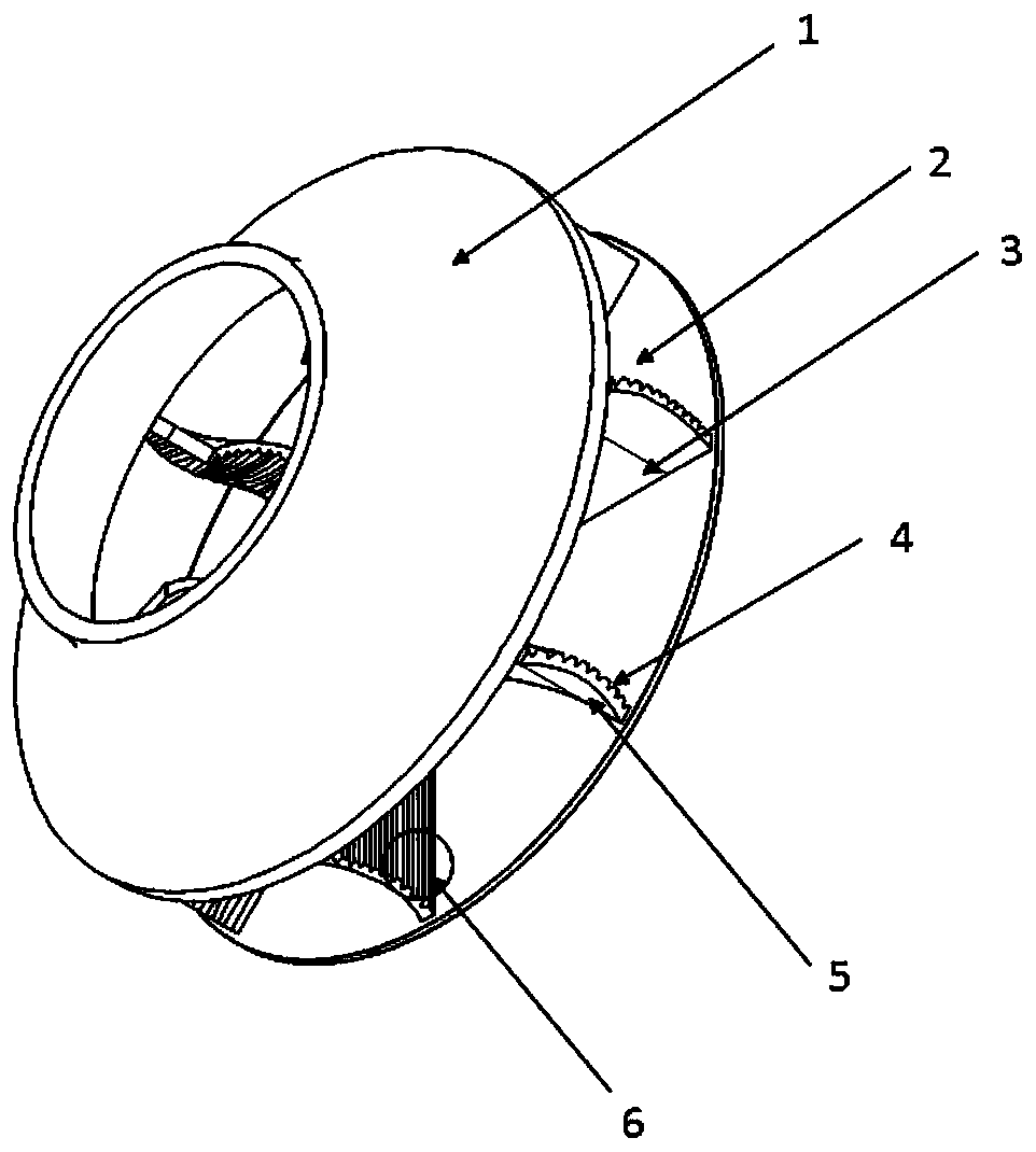
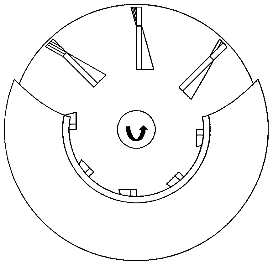
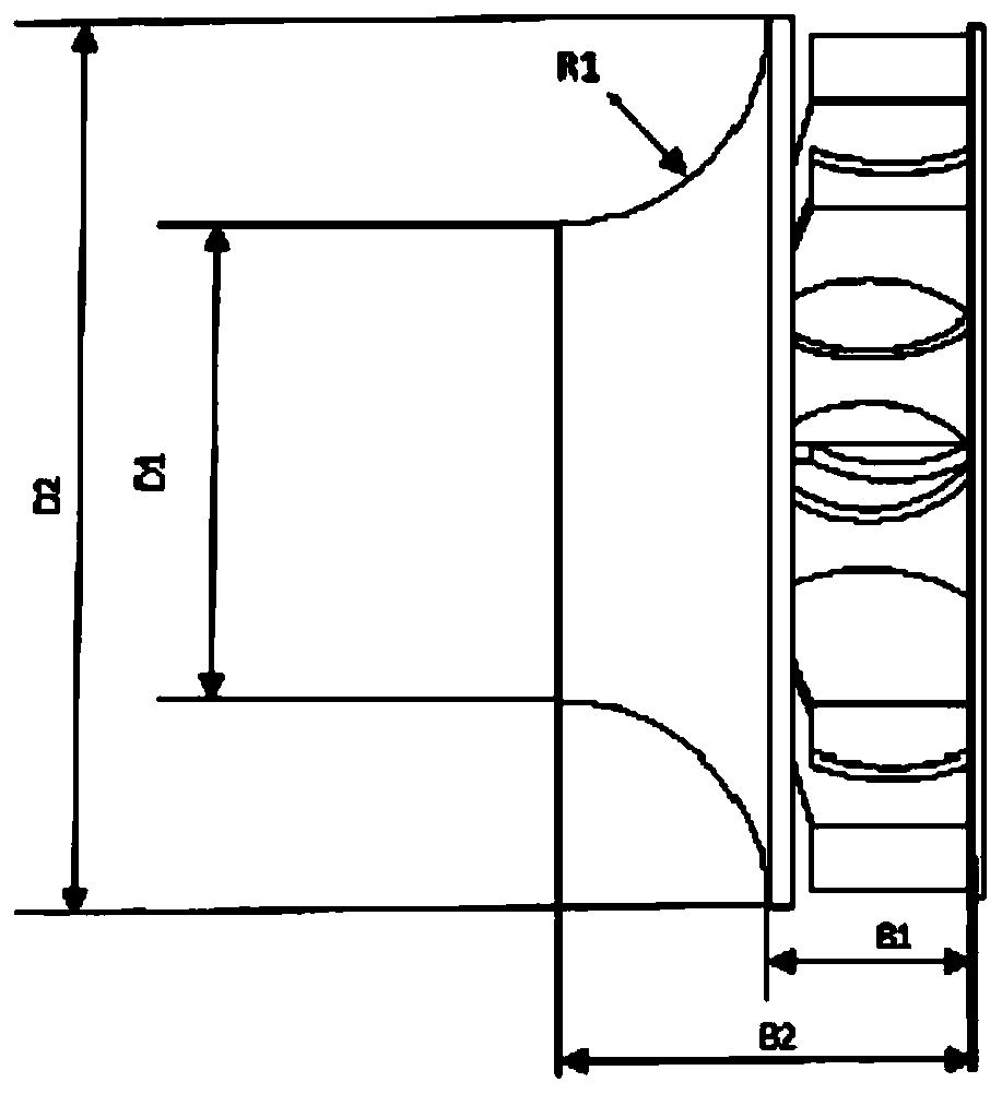
[0034] The invention provides a centrifugal fan impeller, such as Figure 1-3 As shown, the impeller includes a front disk 1, a rear disk 2 and blades 3, wherein the blade 3 has a blade pressure surface 4 and a blade suction surface 5, and its upper and lower end surfaces are fixed and formed by welding with the front disk 1 and the rear disk 2 respectively. There are a plurality of blades 3 inside, and the plurality of blades 3 are arranged in the impeller at intervals along the circumference of the impeller, and the height of the entire impeller is B2.

[0035] Such as image 3 , 4 As shown, the front disc 1 is a ring structure with a bell mouth shape, and the inner diameter of the ring is D1, wherein the value range of D1 is 500mm-2000mm; the section of th...


PUM


Abstract

The invention relates to the technical field of power machinery, in particular to a centrifugal draught fan impeller. The impeller comprises a front disc, a rear disc and multiple blades, the blades are arranged in the impeller in the circumferential direction of the impeller at intervals, the upper and lower end faces of the blades are fixedly connected with the front disc and the rear disc respectively, each blade is provided with a blade pressure face and a blade suction face, each blade is divided into a forward blade and a backward blade in the length direction of the blade, wherein two thirds of section from an air inlet to the blades is a forward blade profile, and the back one third of section is a backward blade profile. The blades in the impeller not only combines the disadvantages of the forward blade profile and backward blade profile, but also is equidistantly provided with V-shaped groove structure on a pressure surface of the backward blade. The centrifugal draught fan impeller has the advantages that surface load of the blades in the impeller are uniformly distributed, the unbalanced vibration is reduced, the turbulent state of the gas of boundary layers of the blades is increased, and the probability and energy of particles hitting the surfaces of the blades are reduced, thereby playing roles in vibration attenuation and erosion resistance.

Description

technical field [0001] The invention relates to the technical field of power machinery, in particular to a centrifugal fan impeller. Background technique [0002] Common centrifugal fans include large industrial blowers, ventilators, gas blowers, coke oven blowers, etc. These centrifugal fans are widely used in metallurgy, building materials, petrochemical and nuclear power and other fields. The gases transported by these industries often contain smoke, solid catalysts, etc. A large amount of particulate matter such as debris, these substances are eroded by gas-solid two-phase flow on the surface of the fan blades, resulting in rapid wear of the fan blades, so improving the working efficiency of centrifugal fans and increasing the erosion resistance of their blades is of great concern to the fan industry and urgent problems to be solved. [0003] At present, the latest fan blade technology uses three-dimensional curved and twisted blades. The curved shape of this blade can ...

Claims


Application Information

Patent Timeline
Patent Type & Authority Patents(China)
IPC IPC(8): F04D29/28F04D29/30F04D29/66
CPCF04D29/281F04D29/30F04D29/666
Inventor 韩志武张帅军张俊秋王大凯牛士超尹维陈文娜陈思琪王可军陈道兵穆正知李博冯晓明王泽孙涛侯涛叶军锋韩奇钢
Owner JILIN UNIV
Why Eureka
Try Eureka