Eureka AIR delivers breakthrough ideas for toughest innovation challenges, trusted by R&D personnel around the world.

Carbon powder slurrying device

A chemical device and carbon powder slurry technology, applied in transportation and packaging, chemical instruments and methods, chemical/physical processes, etc., can solve the problems of harsh production site environment, harmful occupational health, low adsorption efficiency, etc., and achieve good mixing effect , high utilization rate of toner and low production cost

Pending Publication Date: 2020-09-08
云锡文山锌铟冶炼有限公司
View PDF0 Cites 0 Cited by
  • Summary
  • Abstract
  • Description
  • Claims
  • Application Information

AI Technical Summary

Problems solved by technology

The traditional method of adding carbon powder is mostly to directly add to the reaction tank or the liquid inlet chute. This method of adding carbon powder is easy to float on the surface of the solution and is difficult to mix into the solution, resulting in low adsorption efficiency, and part of the carbon powder enters the atmosphere through the air duct of the reaction tank. Causes the loss of carbon powder and pollutes the environment; the dust is serious during the adding process, the production site environment is harsh, and it is harmful to occupational health
[0003] This shows that the existing carbon powder and solution mixing device still needs to be improved

Method used


Image

  • Carbon powder slurrying device

Examples


Embodiment Construction

[0022] Embodiments of the present invention are described in detail below, examples of which are shown in the drawings, wherein the same or similar reference numerals designate the same or similar elements or elements having the same or similar functions throughout. The embodiments described below by referring to the figures are exemplary and are intended to explain the present invention and should not be construed as limiting the present invention.

[0023] In describing the present invention, it should be understood that the terms "center", "longitudinal", "transverse", "length", "width", "thickness", "upper", "lower", "front", " The orientation or positional relationship indicated by "rear", "left", "right", "vertical", "horizontal", "top", "bottom", "inner", "outer", etc. is based on the orientation shown in the drawings Or positional relationship is only for the convenience of describing the present invention and simplifying the description, but does not indicate or imply...


PUM


Abstract

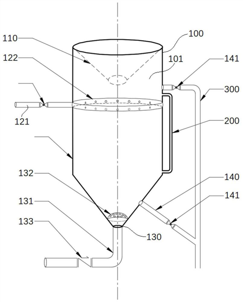
The invention discloses a carbon powder slurrying device. The carbon powder slurrying device comprises a body, an accommodating space is defined in the body, a conical feeding hopper is arranged at the upper part of the body, a liquid inlet structure is arranged in the middle of the body, the lower part of the body is conical, an air inlet and a pneumatic stirring structure are arranged at the conical bottom, a liquid outlet pipeline is arranged at the conical side part, the liquid inlet structure comprises an external liquid inlet pipeline arranged in the middle of the body and an internal annular liquid inlet pipeline arranged on the inner wall of the middle of the body, liquid outlets are distributed in the internal annular liquid inlet pipeline, the pneumatic stirring structure comprises a compressed air pipeline and a spherical sieve plate, the compressed air pipeline is connected with the air inlet, and the spherical sieve plate is arranged at the air inlet. According to the carbon powder slurrying device, by optimizing the structural design, carbon powder and a solution can be rapidly mixed and fully stirred and slurried, flying dust cannot be generated, and the carbon powder slurrying device has the advantages of being easy to operate, capable of saving investment, environmentally friendly, uniform in solid-liquid mixing, high in carbon powder utilization rate, low in unit consumption, low in production cost and the like.

Description

technical field [0001] The invention relates to the field of hydrometallurgy, in particular, the invention relates to a carbon powder slurrying device. Background technique [0002] During the zinc hydrometallurgy process, organic matter in the system will continue to be enriched (brought in by raw and auxiliary materials, leakage of equipment lubricating oil or brought in by maintenance), which will eventually lead to "burning" of organic matter in the electrowinning process, greatly reducing current efficiency and increasing DC power consumption increases production costs and can cause huge economic losses in severe cases. In order to open the organic matter in the wet system, activated carbon powder (hereinafter referred to as carbon powder) is usually added to absorb and remove oil during the solution purification process. The traditional method of adding carbon powder is mostly to directly add to the reaction tank or the liquid inlet chute. This method of adding carbon...

Claims


Application Information

Patent Timeline
Patent Type & Authority Applications(China)
IPC IPC(8): B01F13/02B01F15/02B01F33/40
CPCB01F33/406B01F33/409B01F35/712B01F35/75
Inventor 陈先友朱北平孔正国姚应雄高占勋李科陈钢陶家荣杨瑗孙玉文何成道席阳
Owner 云锡文山锌铟冶炼有限公司
Why Eureka
Eureka Blog
Learn More