Eureka AIR delivers breakthrough ideas for toughest innovation challenges, trusted by R&D personnel around the world.

Porous part boring method and equipment thereof

A technology for parts and boring, applied in drilling/drilling equipment, turning equipment, boring/drilling and other directions, can solve the problem of increasing boring processing cost, small radial clearance of guide sleeve, unable to ensure processing accuracy, and inability to Repair and other problems to achieve the effect of improving production efficiency, preventing friction and heating, and improving machining accuracy

Inactive Publication Date: 2012-12-19
BAODING BIAOZHENG MACHINE TOOL
View PDF6 Cites 3 Cited by
  • Summary
  • Abstract
  • Description
  • Claims
  • Application Information

AI Technical Summary

Problems solved by technology

[0003] This process method has the following disadvantages: 1. The reaming process must be processed from both sides of the hole. Due to the small diameter of the processed aperture and the relatively close distance between the centers of the holes between each row of bosses, the drill pipe When the intermediate guide sleeve is used, the radial clearance of the guide sleeve of the drill pipe is too small to ensure the machining accuracy
2. The reaming knife is a forming knife. After the tool is worn out, it cannot be repaired. It can only be used once and then scrapped; because the axial distance between the processed holes is long, the required tool length must meet the requirements of use, which increases the boring time. Hole processing cost

Method used


Image

  • Porous part boring method and equipment thereof
  • Porous part boring method and equipment thereof

Examples


Embodiment Construction

[0014] The present invention will be further described in detail below in conjunction with the accompanying drawings and specific embodiments.

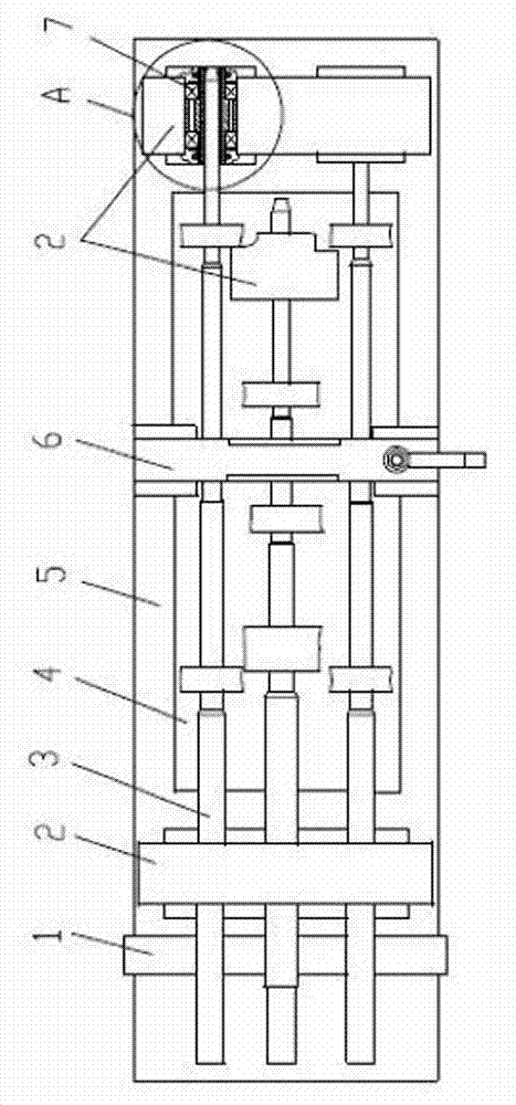
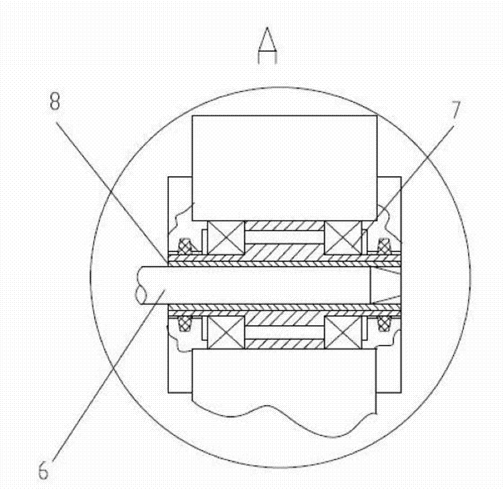
[0015] control figure 1 and figure 2 The operation and use steps of the present invention are further described: a method for boring a porous part, the method comprising: a step of boring a porous part 4 with a horizontal boring machine; The rod 3 is positioned, and the boring bar 2 drives the rotating guide sleeve 8 of the internal bearing 7 of the boring plate 2 to rotate during the cutting process, and at the same time moves horizontally in the rotating guide sleeve 8 .

[0016] The blank of the porous part 4 is fixed on the workbench 5, the boring bar 3 is moved out in the main shaft of the boring machine, one end of the boring bar 3 is connected with the main shaft clamp of the boring machine, and the two ends of the boring bar 3 are located inside the boring template 2 In the rotating guide sleeve 8 of the bearing 7, the bori...


PUM


Abstract

The invention discloses a porous part boring method and equipment of the porous part boring method. The method comprises the step of boring a porous part by using a horizontal boring mill. The method is characterized in that boring templates positioned at both ends of a boring rod are used for positioning the boring rod; and the boring rod drives guide sleeves of bearings inside the boring templates to rotate and moves horizontally in the guide sleeves at the same time during the cutting process. The boring equipment for the porous part comprises a horizontal-type special multi-shaft boring mill, the boring rod and the boring templates. The boring equipment is characterized in that the bearings are arranged in the boring templates; the rotary guide sleeves are embedded into inner holes in the inner circles of the bearings; and transition fit is formed between the outer circle of the boring rod and the inner diameter of each rotary guide sleeve. The method has the advantages that the positioning of the boring rod is accurate, and the rotary guide sleeves guide the boring rod in a rotating manner during the boring process, so that the temperature rise caused by the friction of the boring rod is avoided, and the machining precision and the production efficiency are improved.

Description

technical field [0001] The invention relates to the technical field of boring processing of porous parts, in particular to a method for boring porous parts with accurate positioning of a boring bar, a rotating guide sleeve that can guide the boring bar during the boring process, and preventing frictional heating of the boring bar. equipment. Background technique [0002] The bottom plate of the sewing machine is a porous part. The structural characteristics of this part are: there are longitudinal rows of bosses distributed on the plane of the bottom plate, and each boss is provided with a hole. The center line of the hole is parallel to the plane of the bottom plate. The holes on the boss are concentric, and this part requires high precision for the mechanic. In the prior art, the processing method of this sewing machine bottom machine is to drill holes with a drill press, then expand and hinge. [0003] This process method has the following deficiencies: 1. The hole ream...

Claims


Application Information

Patent Timeline
Patent Type & Authority Applications(China)
IPC IPC(8): B23B35/00B23B39/02B23B49/00B23B27/00
Inventor 甄秀仙陈庆雪唐志学
Owner BAODING BIAOZHENG MACHINE TOOL
Why Eureka
Eureka Blog
Learn More