Sliding friction sheet replacement method and device of wind driven generator yaw system
A wind turbine, sliding friction technology, applied in metal processing, metal processing equipment, manufacturing tools, etc., can solve the complex technology and safety of the sliding friction plate of the yaw system, the wear of the sliding friction plate of the yaw system, and no patent documents have been found. Report and other issues to achieve the effect of saving economic costs, ensuring safety, and saving time and costs
- Summary
- Abstract
- Description
- Claims
- Application Information
AI Technical Summary
Problems solved by technology
Method used
Image
Examples
Embodiment 1
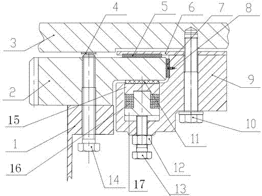
[0017] attached figure 1 A specific implementation method and device for replacing the upper friction plate 5 and the lower friction plate 11 mentioned in the present invention are schematically shown. It can be seen from the accompanying drawings that the wind turbine yaw system includes a yaw ring gear 2 fixed on the upper flange 1 of the wind turbine tower, the two are connected by bolts, and the yaw system further includes bonding The upper friction plate 5 in the friction plate mounting plate 6, the upper and lower surfaces of the friction plate mounting plate 6 are respectively in contact with the lower surface of the nacelle bottom plate 3 of the wind-driven generator and the upper surface of the yaw caliper 9, through the connecting bolt 10 The above three are connected and tightened, and the yaw system further includes a side friction plate 7 fixed on the side of the yaw caliper 9 with a fastening screw 8 and placed in the cavity of the yaw caliper 9 through a compres...
Embodiment 2
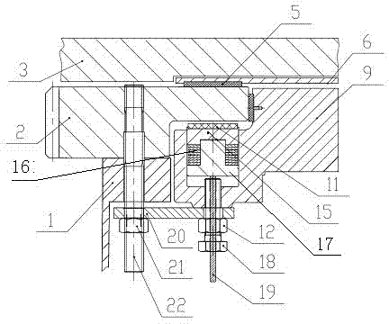
[0020] attached figure 2 Another embodiment of the present invention is schematically shown, which is a specific implementation method and device for replacing the upper friction plate 5 and the lower friction plate 11 . It can be seen from the accompanying drawings that the basic structure of Embodiment 1 is the same, except that the adjustment bolts of the lower friction plate 11 are different. The adjustment bolts are hollow bolts 18, and there is a through hole in the center of the hollow bolt 18. A round iron rod 19 is inserted inside.
[0021] When replacing the lower friction plate 11 and side friction plate 7 of the yaw system (see attached figure 2). Replace a bolt connecting the yaw ring gear 2 and the upper flange 1 of the tower near the yaw caliper 9 with a custom-made screw 22, one end of which is screwed into the threaded hole of the yaw ring gear 2, and the other end is screwed with a Nut 21; a custom-made perforated supporting plate 20 is placed on the upp...
PUM
 Abstract
Description
Claims
Application Information
 - R&D
- Intellectual Property
- Life Sciences
- Materials
- Tech Scout
- Unparalleled Data Quality
- Higher Quality Content
- 60% Fewer Hallucinations
Browse by: Latest US Patents, China's latest patents, Technical Efficacy Thesaurus, Application Domain, Technology Topic, Popular Technical Reports.
© 2025 PatSnap. All rights reserved.Legal|Privacy policy|Modern Slavery Act Transparency Statement|Sitemap|About US| Contact US: help@patsnap.com


