Turntable sensing element with adjustable magnetic fluxes of magnetic blocks and points

A technology of sensing elements and magnetic flux, applied in power metering, vehicle components, torque metering, etc., can solve problems such as inconsistency, difference, and easy signal drift caused by merging control signals

Inactive Publication Date: 2012-12-19
CHONGQING SINYM TECH CO LTD
View PDF10 Cites 0 Cited by
  • Summary
  • Abstract
  • Description
  • Claims
  • Application Information

AI Technical Summary

Problems solved by technology

[0016] Disadvantages (1) Using two permanent magnets with no difference to represent the fixed positions of the two pedals, only multiple Halls can be used to represent the rotational positions of the pedals: the two permanent magnets have no difference, and the advantages It is possible to indicate the fixed position of the two pedals regardless of the left and right feet, so that the left and right feet can generate power assistance requirements, which can produce the same motor power assistance effect; but the disadvantage is that the permanent magnet itself cannot indicate the rotation position of the pedals, but only Multiple Halls can be set at different corner positions to indicate the rotational position of the pedal, so one Hall cannot be used, but multiple Halls must be used
[0017] Disadvantage (2) You can’t use only one Hall, but three Halls will inevitably cause the original segmentation error of the three control signals, which will distort the power-assisted demand model, and naturally produce power-assisted output inconsistent with the power-assisted demand: whether the power-assisted bicycle is one or two For a motor, the sensing signal for controlling the motor can only be achieved by inputting a sensing signal into the motor controller to achieve the purpose of controlling the motor; while the patent uses three Halls to control the motor, it is necessary to use the three Halls of the three Halls to control the motor. The signals are combined into one combined control signal before being input to the motor controller
The sensing parameters of the three Halls cannot be the same, especially due to changes in ambient temperature and long-term use, the sensing parameters of the three Halls may vary greatly. The output voltages are different, resulting in different power output of the motor, and the power output is inconsistent with the power demand; similarly, when the power demand is the same, the outputs of different Halls may be the same voltage, resulting in the same power output of the motor, and also There is a problem that the power output is inconsistent with the power demand
[0018] Disadvantage (3) The combined control signal is prone to signal drift, which makes the combined control signal not match the motor controller, and the power-assisted demand model is distorted: due to changes in ambient temperature and long-term use, the sensing parameters of the three Halls may vary greatly , the connection points of the three control signals of the three Halls must change, then the combined control signals generated by the same boost demand will produce segmental signal drift, and the combined control signals will produce signal distortion as a whole, that is, the power boost demand model distortion , causing the motor controller to choose any one of the three control signals as a reference will cause the problem that the power output is inconsistent with the power demand
[0019] Disadvantages The sensing points cannot be increased arbitrarily. If there are too few sensing points, the motor will not run smoothly, which will make the rider feel very uncomfortable: due to the disadvantages (1) and (2), it is most important because the number of Halls is greater than A cause, obviously the more the number of Halls, the more serious the disadvantages (1) and (2)
Therefore, the power-assisted bicycle provided by this patent can only be a very bad power-assisted bicycle that makes the rider feel comfortable.
[0020] Disadvantage (5) The blind area of ​​the signal is up to 42 degrees, and you can't get it when you need it when you start it: As we all know, the torque of the bicycle pedal is the smallest at the apex, and the 10-45 degrees away from the apex is the area that needs the most assistance. , but the included angle between the Halls in this patent is 42.5-43.5 degrees. There is no Hall in the area where the pedal is 10-42 degrees away from the apex, and there is no control signal. The result is when the power is most needed , but the motor of the power-assisted bicycle does not assist
[0021] In short, this patent is a technical solution for using multiple Halls to control the booster mode, because only multiple Halls can be used to represent the rotation position of the pedal, and the multiple control signals of multiple Halls must have original errors, and the combined control signals It is also easy to produce signal drift, which can cause distortion of the assist demand model, that is, the same assist demand at different times, but different assist effects; the more the number of Halls, the more serious the distortion of the assist demand model, which limits the number. If the amount of Hall is too small, the motor will not run smoothly, which will make the rider feel very uncomfortable, and will not be assisted when starting.
To make it undistorted to help the demand model, and to ensure the smooth operation of the motor, there are always two issues. It is impossible to have both.

Method used


Image

  • Turntable sensing element with adjustable magnetic fluxes of magnetic blocks and points
  • Turntable sensing element with adjustable magnetic fluxes of magnetic blocks and points

Examples


Embodiment 1

[0067] Embodiment 1. Multi-magnetic blocks and a turntable sensor element with adjustable magnetic flux at each point

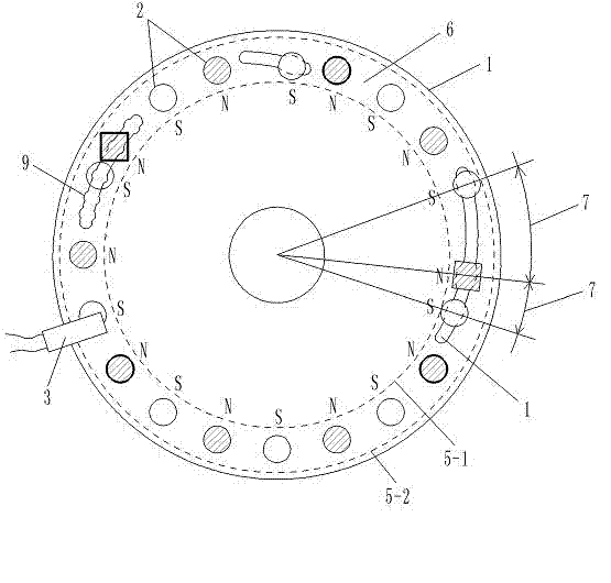
[0068] Such as figure 1 , one surface of a high-strength plastic rotating disk 1 with a diameter of 10.0 cm is set to a diameter of 0.6-0.8 cm, and the magnetic flux is 146---279 (B·H)max / KJ·m -320 permanent magnet blocks 2 with different selection values ​​within the range and unequal magnetic flux of adjacent permanent magnet blocks 2 . The structure of rotating disk 1, permanent magnet block 2 and Hall 3 is as follows:

[0069] Each permanent magnet block 2 is fixed in the circle 6 range between the circular trajectory line 5-1-9.5 centimeters outer circular trajectory line 5-2 with a diameter of 8.5 centimeters, and there are a plurality of permanent magnet blocks 2 that are radially dislocated Distributed, there are a plurality of permanent magnet blocks 2 in dislocation distribution.

[0070] Radius dislocation distribution mode is: the plurality of ...

Embodiment 2

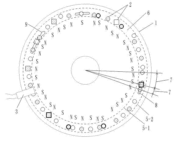
[0077] Embodiment 2. High-density multi-magnetic blocks and a turntable sensor element with adjustable magnetic flux at each point

[0078] Such as figure 2 1. A high-strength aluminum rotating disc 1 with a diameter of 10.0 cm is provided with 40 permanent magnet blocks 2 with a diameter of 0.4-0.6 cm. The magnetic flux of the permanent magnet block 2 is 146---279 (B·H)max / KJ·m -3 Different selection values ​​within the range, and the magnetic flux of the adjacent permanent magnet block 2 is not equal, Hall 3 keeps a distance of 0.2 cm from each permanent magnet block 2 in the rotating state, so that each permanent magnet block 2 that is rotating Hall 3, Hall 3 can generate a corresponding rectangular wave electrical signal output. The circle where the arc of the arc bar hole 8 is located and the inner circular trajectory line 5-1 are concentric circles. The structures of other rotating disk 1, permanent magnet block 2, and Hall 3 are the same as those in embodiment 1.


PUM

PropertyMeasurementUnit
diameteraaaaaaaaaa
diameteraaaaaaaaaa
diameteraaaaaaaaaa

Abstract

The invention discloses a turntable sensing element with adjustable magnetic fluxes of magnetic blocks and points, belongs to the technical field of providing a signal by magnetic induction and particularly relates to a technology for carrying out multi-point magnetic induction to provide a control signal on a rotating component. A plurality of permanent magnet blocks which are distributed in a ring are fixedly arranged on the turntable sensing element; the distances between the permanent magnet blocks can be adjusted and the magnetic fluxes of the permanent magnet blocks at different positions can be adjusted; the magnetic polarities of the adjacent permanent magnet blocks are opposite at one side of the rotating plate, namely the magnetic polarity distribution mode of all permanent magnet blocks at one side of the turntable sensing element is an N pole, an S pole, an N pole ...; and halls are arranged at the positions near the permanent magnet blocks. The turntable sensing element has the advantages that the halls can obtain rectangular wave signals by an opposite distribution mode of the magnetic polarities NS of the adjacent permanent magnet blocks; the signals can be conveniently subjected to digital processing, and the rectangular wave signals can present the positions of the permanent magnet blocks on the rotating plate by difference of the distances and the magnetic fluxes, and uses of different rectangular waves are determined.

Description

technical field [0001] The invention belongs to the technical field of providing signals by magnetic induction, and in particular relates to the technology of providing control signals by multi-point magnetic induction on a rotating component. Background technique [0002] The Chinese patent 201020295192.0 "Claw Type Torque Sensing Device" applied by Yebao Vehicle Material Industry (Kunshan) Co., Ltd. discloses a sensing device for power-assisted bicycles. The sensing device includes a magnetic part and an elastic part to sense the torque. sensing device. After a long time of use, the change of the elastic coefficient of the elastic member will lead to changes in the sensing signal and the control effect of the controlled motor, and the power-assisted effect will not match the power-assisted needs of people. Moreover, the design structure of the elastic member is complex and the manufacturing cost is high. [0003] The Chinese patent 01201843.0 "Automatic Detection Device ...

Claims


Application Information

Patent Timeline
Patent Type & Authority Applications(China)
IPC IPC(8): B62M6/50G01L3/00G01P3/481
Inventor 黄强
Owner CHONGQING SINYM TECH CO LTD
Why Eureka
Try Eureka