Batch refiner and refining process thereof

A refiner, intermittent technology, applied in the field of paper pulping, can solve the problems of redundant equipment, difficulty in adapting to the change of pulp feeding, difficulty in increasing or reducing the grinding area, etc., to save energy, improve efficiency and quality, and high The effect of flow efficiency

Active Publication Date: 2012-12-19
山东惠祥专利造纸机械有限公司
View PDF8 Cites 7 Cited by
  • Summary
  • Abstract
  • Description
  • Claims
  • Application Information

AI Technical Summary

Problems solved by technology

[0007] In order to solve the problem that the beater in the prior art is in order to improve the beating degree of pulp, the problem of redundant equipment exists when setting multiple beaters in series or setting multiple gri

Method used


Image

  • Batch refiner and refining process thereof
  • Batch refiner and refining process thereof
  • Batch refiner and refining process thereof

Examples


Embodiment 1

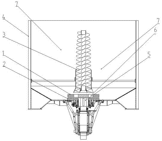
[0057] The batch refiner described in this embodiment, such as figure 1 shown, including:

[0058] A housing 4, on which a pulp inlet and a pulp outlet that can be controlled to be switched on and off are provided;

[0059] The grinding table includes a coaxially arranged moving grinding table 2 and a fixed grinding table 1, the moving grinding table 2 and the fixed grinding table 1 are arranged in the housing 4, and a refining gap is arranged between the moving grinding table 2 and the fixed grinding table 1;

[0060] The transmission shaft 5 is coaxially connected with the moving grinding table 2, and drives the moving grinding table 2 to rotate synchronously;

[0061] Gap adjustment mechanism, used to adjust the gap between the movable grinding disc 2 and the fixed grinding disc 1;

[0062] The pushing flow device 3 is arranged in the housing 4, and the liquid inlet channel 6 is arranged on the fixed grinding plate 1, and the liquid inlet channel is arranged through the t...

Embodiment 2

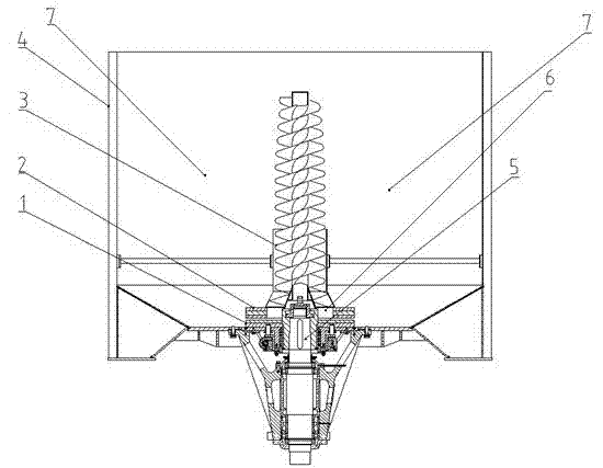
[0072] The batch refiner described in this embodiment, such as figure 2 shown, including:

[0073] A housing 4, on which a pulp inlet and a pulp outlet that can be controlled to be switched on and off are provided;

[0074] The grinding table includes a coaxially arranged moving grinding table 2 and a fixed grinding table 1, the moving grinding table 2 and the fixed grinding table 1 are arranged in the housing 4, and a refining gap is arranged between the moving grinding table 2 and the fixed grinding table 1;

[0075] The transmission shaft 5 is coaxially connected with the movable grinding table 2 and drives the moving grinding table 2 to rotate synchronously;

[0076] Gap adjustment mechanism, used to adjust the gap between the movable grinding disc 2 and the fixed grinding disc 1;

[0077] The pushing flow device 3 is arranged in the housing 4, and the liquid inlet channel 6 is arranged on the moving grinding table 2, and the liquid inlet channel 6 is arranged through t...

Embodiment 3

[0087] A kind of intermittent refiner of the present invention, such as figure 2 shown, including:

[0088] A housing 4, on which a pulp inlet and a pulp outlet that can be controlled to be switched on and off are provided;

[0089] The grinding table includes a coaxially arranged moving grinding table 2 and a fixed grinding table 1, the moving grinding table 2 and the fixed grinding table 1 are arranged in the housing 4, and a refining gap is arranged between the moving grinding table 2 and the fixed grinding table 1;

[0090] The transmission shaft 5 is coaxially connected with the movable grinding table 2 and drives the moving grinding table 2 to rotate synchronously;

[0091] Gap adjustment mechanism, used to adjust the gap between the movable grinding disc 2 and the fixed grinding disc 1;

[0092] The pushing flow device 3 is arranged in the housing 4, and the liquid inlet channel 6 is arranged on the moving millstone 2, and the liquid inlet channel is arranged through t...


PUM

PropertyMeasurementUnit
Tensile strengthaaaaaaaaaa

Abstract

The invention provides a batch refiner which comprises a shell, a moving refining plate, a fixed refining plate, a transmission shaft and a gap adjusting mechanism, wherein the moving refining plate and the fixed refining plate are coaxially arranged, and the transmission shaft is coaxially connected with the moving refining plate. The batch refiner is further provided with a fluid pushing device, a fluid inlet channel is arranged on the moving refining plate or the fixed refining plate and penetrates through two bottom surfaces of the moving refining plate or the fixed refining plate, a discharge end face of the fluid pushing device faces the fluid inlet channel, and communicated backflow gaps are reserved between the fluid pushing device and the shell as well as between each refining plate and the shell respectively. Multiple refining can be achieved by circulating pulp between the refining plates when the batch refiner is operated, and times of refining are not limited by the batch refiner; and gaps between the refining plates can be adjusted by the gap adjusting mechanism so as to adapt to changes of the pulp. The batch refiner is simple and flexible in operation.

Description

technical field [0001] The invention belongs to the field of papermaking and pulping, and in particular relates to a batch refiner and a refining process thereof. Background technique [0002] In the paper industry, the pulp from the pulping process cannot be used directly for papermaking, but must be beaten first, because the pulp fibers at this time are stiff and elastic, and contain a large number of unseparated fiber bundles, which are hard , and some are too long, some are too thick, and lack the necessary cutting and separation. If they are used to make paper, the resulting products will be loose, porous, rough in surface and low in hardness, which cannot meet the requirements of use. Hydraulic beating is the use of mechanical devices to process pulp fibers in water, and perform mechanical actions such as extrusion, kneading, cutting, and carding on the fibers to make the fibers undergo various morphological changes such as cutting, splitting, brooming, and swelling, s...

Claims


Application Information

Patent Timeline
IPC IPC(8): D21D1/30
Inventor 李昊
Owner 山东惠祥专利造纸机械有限公司
Why Eureka
Try Eureka