Oiling device for spring part of clock

An oiling device and clock spring technology, which is applied to engine components, engine lubrication, mechanical equipment, etc., can solve problems such as uneven coating surface, low work efficiency, and short life, so as to achieve uniform oiling surface and improve efficiency , the effect of improving the service life

Inactive Publication Date: 2012-12-19
昌辉汽车电器(黄山)股份公司
View PDF7 Cites 6 Cited by
  • Summary
  • Abstract
  • Description
  • Claims
  • Application Information

AI Technical Summary

Problems solved by technology

[0005] The purpose of the present invention is to provide an oiling device for clock spring parts, which solves the problems of uneven coating surface, low working efficiency and short service life

Method used


Image

  • Oiling device for spring part of clock
  • Oiling device for spring part of clock
  • Oiling device for spring part of clock

Examples


Embodiment 1

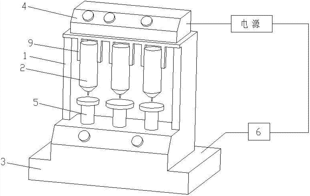
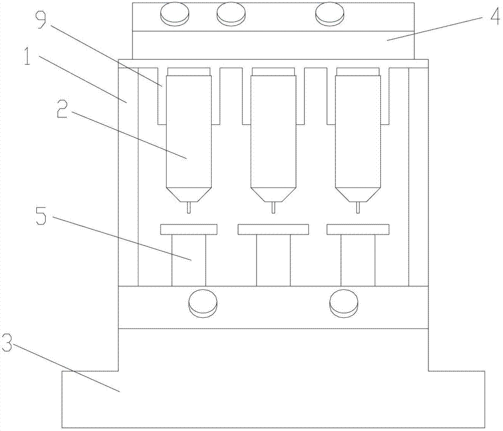
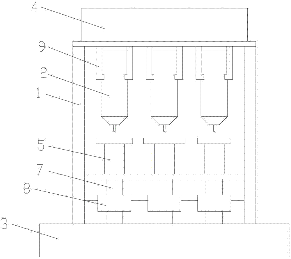
[0022] Please also refer to Figure 1 to Figure 3 , as shown in the figure, the oiling device for clock spring parts includes a base 3, a housing 1 arranged on the base 3, a spraying assembly installed on the housing 1, and the spraying assembly further includes an oiling pipe 2 and a The fixing frame 9 for fixing the oiling pipe 2; also includes the air pressure regulator 4 arranged above the casing 1 and providing pressure to the inside of the oiling pipe 2, the driving mechanism installed on the base 3, and the synchronous servo motor 6 that drives the driving mechanism to work , the turntable 5 driven by the driving mechanism, the turntable 5 is arranged directly below the oiling pipe 2, and the synchronous servo motor 6 and the air pressure regulator 4 are connected to the power supply. The driving mechanism also includes a rotating rod 7 with one end arranged at the bottom of the turntable 5 and the other end connected to the base 3 , and a gear 8 sleeved on the rotating...

Embodiment 2

[0024] see Figure 4 , on the basis of Embodiment 1, at least two groups of spraying assemblies are arranged on the oiling device, and three groups of spraying assemblies are shown in the figure, and a corresponding turntable 5 is arranged directly below the oiling pipe 2 of each group of spraying assemblies, Moreover, in order to prevent the oil mist sprayed by each group of spraying components from interfering, a baffle plate 10 is arranged between each group of spraying components, and the baffle plate 10 is fixedly arranged on the housing 1 .

[0025] A working air pressure is pre-set inside the oiling pipe 2 through the air pressure regulator 4. Driven by the synchronous servo motor 6, the turntable 5 rotates one revolution, and the clock spring component rotates synchronously on the turntable 5. When the parts rotate, the oiling pipe 2 The grease inside is injected under the pressure of the air pressure and coated on the surface of the parts, and the oiling is also compl...


PUM


Abstract

The invention discloses an oiling device for a spring part of a clock. The oiling device for the spring part of the clock comprises a base, a shell arranged on the base and a spraying assembly installed on the shell. The spraying assembly further comprises an oiling tube and a fixed frame for fixing the oiling tube. The oiling device further comprises a pressure adjustor arranged above the shell for providing pressure for the oiling tube, a driving mechanism installed on the base, a synchronous servo motor driving the driving mechanism to work and a rotary table driven by the driving mechanism. The rotary table is arranged right below the oiling tube. The oiling device for the spring part of the clock provided by the invention uses gear transmission and is simple in structure, and not only is the surface of the spring part of the clock oiled uniformly and the work efficiency improved, but also the service life of the device is prolonged, and the oiling efficiency of the spring part of the clock is improved. A baffle is further arranged in the oiling device with a plurality of spraying assemblies so that oil mists sprayed by the oiling tubes of different spraying assemblies are effectively blocked, interference among the oil mists is prevented, and the demand of meeting the actual production is better met.

Description

technical field [0001] The present invention relates to an oiling device, in particular to an oiling device for clock spring parts. Background technique [0002] The clock spring is the key electrical rotary connection part used in the car airbag. Through the special winding structure of the internal flexible flat cable, the steering wheel can be retracted and retracted normally when it is turned left and right, ensuring that all connections are made through the clock spring when the steering wheel is turned. The electrical functions of the clock spring are normally implemented. The clock spring includes a flexible flat cable, a casing, a turning block and a back cover. In order to prolong the service life of the clock spring and reduce internal friction, it is necessary to apply lubricating grease to the matching parts of the casing, turning block and the back cover. . The oiling of clock spring parts is generally manual operation at present, and this method has high labor...

Claims


Application Information

Patent Timeline
Patent Type & Authority Applications(China)
IPC IPC(8): F16N7/00
Inventor 王进丁王正成朱排进李宏志
Owner 昌辉汽车电器(黄山)股份公司
Why Eureka
Try Eureka