

Milling tool as well as segment therefor
A milling cutter and cutter body technology, applied in the field of milling cutters and cutter segments, can solve the problems of insufficient machining accuracy, cumbersomeness, complex adjustment and grinding of cutter segments, etc., and achieve simple installation and disassembly, high positioning reliability, high The effect of dimensional accuracy
- Summary
- Abstract
- Description
- Claims
- Application Information
AI Technical Summary
Problems solved by technology
Method used
Image

Examples
Embodiment Construction
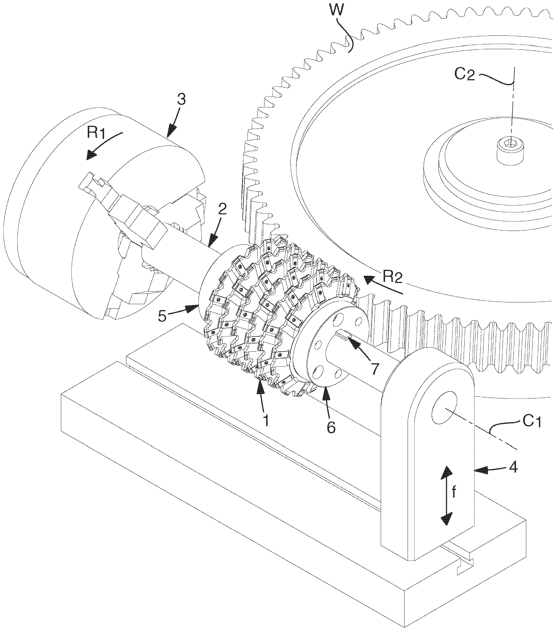
[0029] exist figure 1 , schematically shows a milling cutter 1 manufactured according to an embodiment of the invention during the machining of a workpiece W for the purpose of forming a cog (for clarity, the cog and notch are shown in the final machining state ). In other words, the invention is exemplified in the form of a segmented hob. In this example, the tool 1 is mounted on a shaft 2 whose central axis is designated C1 and which is clamped at one end in a chuck 3 and at the opposite end in a support bracket 4 . The segments which together form the milling cutter 1 are placed between a pair of end pieces, one of which is designated 5 and the other end piece is designated 6 . In order to transmit the torque from the drive shaft 2 to the tool 1, the wedge 7 is countersunk in a groove on the drive shaft and engages with an internal groove in the different segments. While the workpiece W can be turned or rotated in the direction R2 , more precisely around the center axis ...
PUM
 Abstract
Description
Claims
Application Information