Fixture structure for glass mould machining

A technology of glass molds and fixtures, which is applied in the field of fixtures and fixtures. It can solve the problems of fragility and glass molds, difficult to guarantee quality, and affect the smoothness of the mold cavity. It achieves the effect of convenient and fast operation, simple structure, and guaranteed carving quality and efficiency.

Active Publication Date: 2012-12-26
CHANGSHU JIANHUA MOLD TECH
View PDF6 Cites 32 Cited by
  • Summary
  • Abstract
  • Description
  • Claims
  • Application Information

AI Technical Summary

Problems solved by technology

However, due to the lack of a suitable fixture structure that enables the glass mold to be put into a machining center for engraving under an ideal clamping state in the prior art, electric discharge machining is generally used, but there are the following technical problems in electric discharge machining: one, The processing cost is high, and the processing efficiency is low, so it is difficult to meet the requirements of industrial scale-up production; second, the quality is difficult to guarantee, the depth of the pattern texture is difficult to control, and even the glass mold is easy to be damaged, because the pattern processing, that is, the depth of the carved pattern is superficial, but objective Therefore, if the depth of the pattern texture is improperly controlled and significantly exceeds the depth required by the process, it will leave the glass mold with the risk of cracking during the service process; third, after the impact The smoothness of the surface polishing in the first process, because there are many microscopic concave-convex surfaces on the surface of the pattern after EDM, it is difficult for these concave-convex surfaces to achieve the desired smoothness through polishing, thus affecting the overall smoothness of the mold cavity, and finally affecting the transparency of the glass container. The grade of the glass container cannot be upgraded
[0004] For the above-mentioned prior art, the applicant has searched the literature, but there is no corresponding technical inspiration in the published Chinese and foreign patents and non-patent literature.

Method used


Image

  • Fixture structure for glass mould machining
  • Fixture structure for glass mould machining
  • Fixture structure for glass mould machining

Examples


Embodiment 1

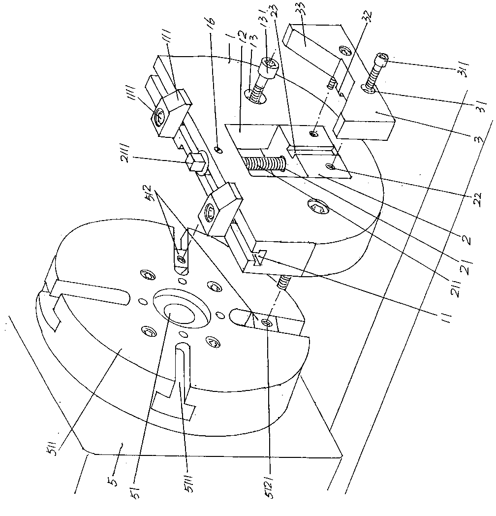
[0022] see figure 1 , in order to facilitate the public's understanding, the applicant in the figure 1 The machine tool 5 is also shown, and a chuck 511 is fixed on the main shaft 51 of the machine tool 5. According to common knowledge, a chuck groove 5111 is opened on the chuck 511, and the number of the chuck grooves 5111 is usually four and a cross section. The shape is T-shaped, and the adjacent chuck grooves 5111 form a 90° relationship with each other. Each of the chuck grooves 5111 is provided with a T-shaped nut 512 , and each T-shaped nut 512 has a nut hole 5121 .

[0023] The overall shape of the base 1 as the technical solution provided by the present invention is in the shape of a semicircle, which can also be called a horseshoe shape. A T-shaped presser foot slide with a cross-sectional shape of an English letter inverted by 180° is provided on the surface of one side of the base 1, that is, the side facing upward in the current position shown in the figur...

Embodiment 2

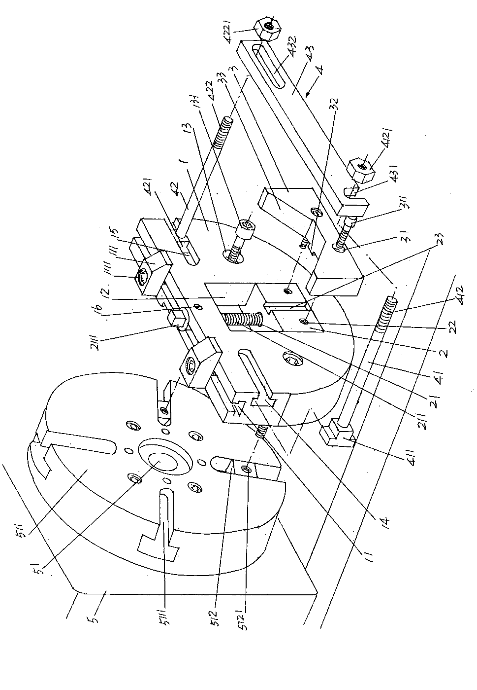
[0030] see figure 2 , because there are differences in the varieties of glass molds 6, for example, the length of the glass molds 6 used for forming glass cans is relatively short, so the structure of Example 1 can be capable of reliably clamping such glass molds 6, while for The length or height of the glass mold 6 for a glass container such as a red wine bottle is relatively long or high, therefore, figure 2 The structure shown is flexible.

[0031] Depend on figure 2 As shown, on the side of the base 1 facing the support module 3 and at the positions corresponding to each other in a horizontal state ( figure 2 The position shown as an example) is provided with a first guide groove 14 and a second guide groove 15, wherein: the first guide groove 14 is located on one side of the sliding cavity 12 of the support module fixing seat mentioned in Embodiment 1 , and the second guide chute 15 is located on the other side of the sliding cavity 12 of the support module f...


PUM


Abstract

The invention belongs to the field of a tool fixture and provides a fixture structure for glass mould machining. The fixture structure comprises a base seat, a pressure foot slide groove is arranged on the surface of one side of the base seat along the length direction of the surface, pressure feet are arranged on the pressure foot slide groove in a matched mode, a supporting mould block fixing seat and a supporting mould block slide cavity are arranged on the base seat, and the positions on the base seat where the supporting mould block fixing seat and the supporting mould block slide cavity are arranged correspond to the lower portion of the center position of the length direction of the pressure foot slide groove; the supporting mould block fixing seat is matched with the supporting mould block slide cavity, a supporting mould block fixing seat nut is arranged on the supporting mould block fixing seat in matched mode, the supporting mould block fixing seat nut is connected with one end of a lifting screw rod of the supporting mould block fixing seat, and the other end of the lifting screw rod of the supporting mould block fixing seat is arranged on the pressure foot slide groove in a supporting mode; a supporting mould block is fixed with one side of the supporting mould block fixing seat, one end of each pressure feet stretches out the surface of one side of the base seat, wherein the end and the surface both face towards the supporting mould block. The fixture structure for the glass mould machining has the advantages that the fixture structure breaks away from a traditional electric spark mode that flower engraving machining is used for a cavity of the glass mould, the flower engraving quality and efficiency are ensured, and the operation is convenient and fast.

Description

technical field [0001] The invention belongs to the technical field of fixtures, and in particular relates to a fixture structure for glass mold processing. Background technique [0002] Fixtures play a very important role in the production of industrial products, and the processing of glass molds is no exception. The so-called tooling fixture refers to special equipment or tools used to clamp or position workpieces in machining to meet certain process requirements. Fixtures usually need to meet the requirements of no interference during product production, accurate and reliable positioning, and convenient operation. Since the tooling fixture has the exclusive characteristics of manufacturing a certain product, the degree of generalization is low, and it is often made by the manufacturer of mechanical products. Glass mold manufacturers also mostly equip various tooling fixtures in a self-made way. In recent years, although all kinds of medium and high-end machining centers...

Claims


Application Information

Patent Timeline
Patent Type & Authority Applications(China)
IPC IPC(8): B23Q3/12
Inventor 晏庆宝韩志强叶进方朝辉
Owner CHANGSHU JIANHUA MOLD TECH
Why Eureka
Try Eureka