Automated positioning of wheels in tyre pressure control systems

A technology for motor vehicles and wheels, which is applied in tire measurement, vehicle parts, transportation and packaging, etc., which can solve the problems of measurement accuracy uncertainty and achieve the effect of improving reliability

Inactive Publication Date: 2012-12-26
HUF HULSBECK & FURST GMBH & CO KG
View PDF10 Cites 11 Cited by
  • Summary
  • Abstract
  • Description
  • Claims
  • Application Information

AI Technical Summary

Problems solved by technology

However, this system of devices has residual uncertainties in the measurement accuracy based on the different placement of the sensors on the tire

Method used


Image

  • Automated positioning of wheels in tyre pressure control systems
  • Automated positioning of wheels in tyre pressure control systems

Examples


Embodiment Construction

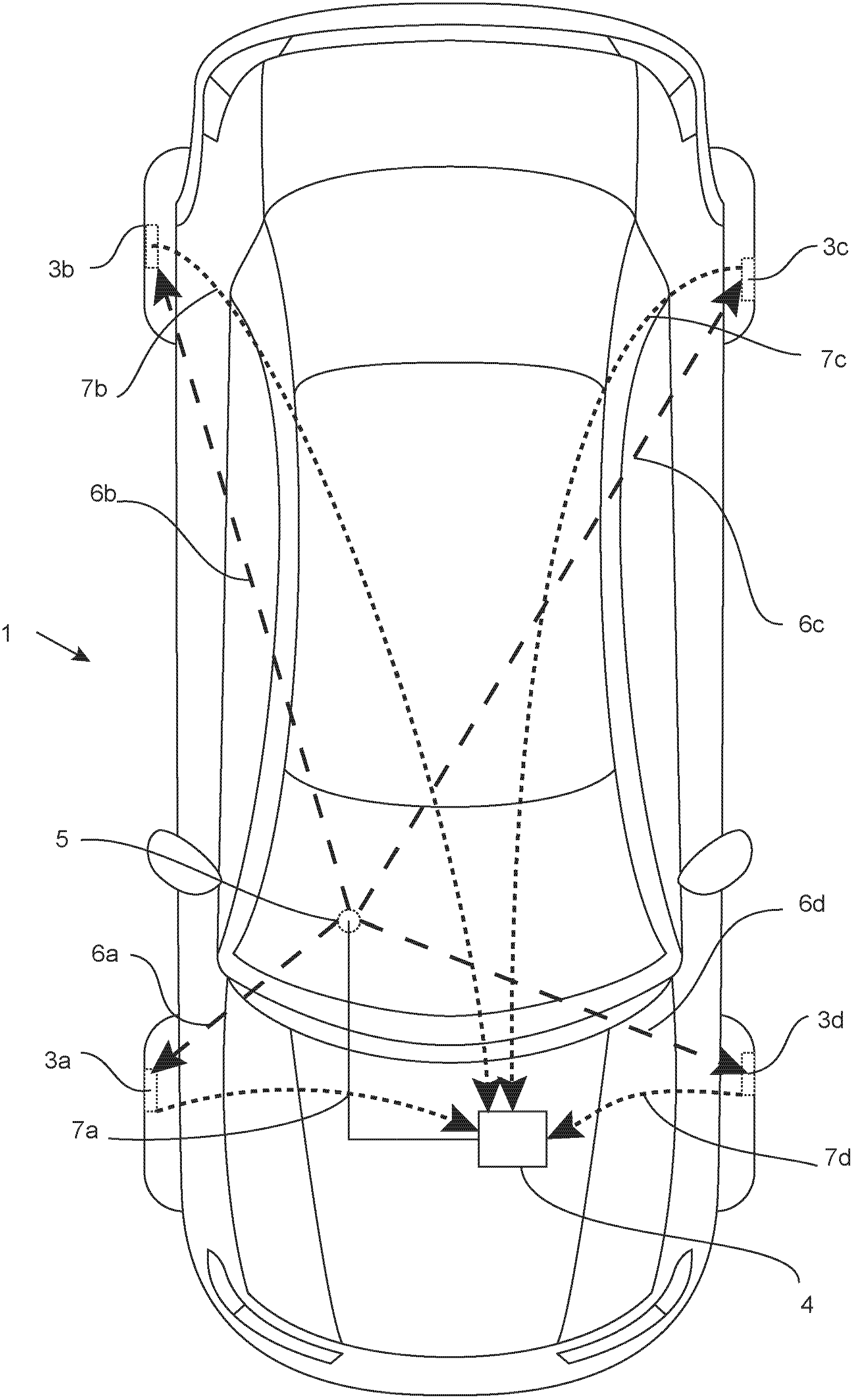
[0026] figure 1 A motor vehicle 1 is shown in , which has tire pressure sensors 3 a , 3 b , 3 c and 3 d on its wheels 2 .

[0027] A control device 4 is embodied on the motor vehicle. An antenna 5 arranged under the vehicle for radiation to the outside area is coupled to the control device 4 . The control device 4 can control the antenna 5 in order to transmit a measurement signal with a frequency of 125 kHz. In this example, the antenna is arranged below the vehicle floor with a certain radiation and is positioned decenter on the vehicle. The antenna 5 is arranged offset both to the longitudinal axis of the vehicle and to the central transverse axis of the vehicle. The antenna 5 has a different distance from each of the pressure sensors 3a, 3b, 3c and 3d. The signal paths from the antenna 5 to the sensors are shown with arrows 6a, 6b, 6c and 6d. Pressure sensors 3 a , 3 b , 3 c and 3 d have mechanisms with which radio communication with central control unit 4 can be carr...


PUM


Abstract

The method involves determining strength of a determination signal by a unit for receiving low-frequency signals (6a-6d) at wheels. High frequency data transmission to a vehicle-sided control device (4) is initiated by the unit for wireless transmission of tire pressure from the wheels, where the data transmission comprises signal strength of the determination signal. Signal strength of the wheels is detected during rolling motion. A wheel-specific average value is formed. The determination signal is sent from antennas (5), which are arranged at a motor car (1) for access control.

Description

technical field [0001] The invention relates to a method and a device for automatically determining the mounting position of a wheel on a motor vehicle equipped with a tire pressure sensor for a tire pressure control system. Background technique [0002] The Tire Pressure Control System (RDKS) or Tire Pressure Monitoring System (TPMS) allows automatic monitoring of the tire pressure of a motor vehicle. The pressure of the individual tires stretched on the wheel can be monitored at discrete points in time or cyclically or continuously and the driver can be warned of a dangerous pressure loss or also excess pressure in the tire. [0003] Within the scope of the present invention is a direct measurement system in which pressure sensors monitor the air pressure in the tires on each wheel. If necessary, the air temperature is also measured in addition to the air pressure. In systems of this type, the tire pressure sensor is designed in such a way that it can communicate with a ...

Claims


Application Information

Patent Timeline
Patent Type & Authority Applications(China)
IPC IPC(8): B60C23/04
CPCB60C23/0416B60C23/0461B60C23/045B60C23/0408
Inventor 斯文・根纳曼约尔格・西蒙埃德温・加西亚・瓦伦祖埃拉
Owner HUF HULSBECK & FURST GMBH & CO KG
Why Eureka
Try Eureka