High-pressure water seal dual-power auger stem

An auger rod, dual power technology, applied in drill pipe, drill pipe, earthwork drilling, etc., can solve the problem of difficult to meet the requirements of high-efficiency deep hole drilling in soft coal seams, with low resistance of the outer flat drill pipe, and fluid slag discharge. Failure and other problems, to achieve the effect of simple structure, good slag discharge effect and high operation efficiency

Active Publication Date: 2012-12-26
CHONGQING UNIV
View PDF5 Cites 9 Cited by
  • Summary
  • Abstract
  • Description
  • Claims
  • Application Information

AI Technical Summary

Problems solved by technology

During the drilling process of the drill pipe, the drill bit breaks the coal in front to open the channel. Although the outer flat drill pipe does not have the effect of driving the coal slag outward, the outer flat drill pipe has a small resistance and has a good effect on maintaining the hole wall. The relatively large slag channel is good for coal slag removal, but when the smooth drill pipe powered by water for slag discharge is drilled in a soft coal seam, the water will soften and expand the coal body, which will easily form a collapsed hole, and the fluid slag discharge channel will be collapsed. The accumulated cinder is blocked, and the fluid slag discharge will fail quickly. Continued drilling will inevitably cause drill sticking and drilling, and it will easily cause drilling combustion when the drill is rotated back.
It can be seen that the high-pressure water-sealed drill pipe with a single power slag discharge method is difficult to meet the requirements of high-efficiency deep-hole drilling in soft coal seams

Method used


Image

  • High-pressure water seal dual-power auger stem
  • High-pressure water seal dual-power auger stem
  • High-pressure water seal dual-power auger stem

Examples


Embodiment Construction

[0025] The technical solutions of the present invention will be described in further detail below with reference to the accompanying drawings and embodiments.

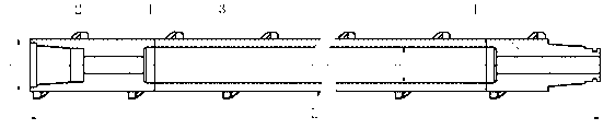
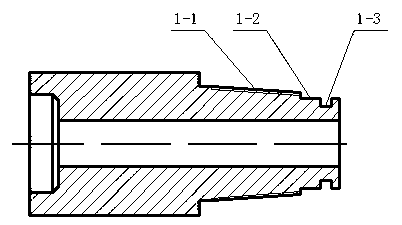
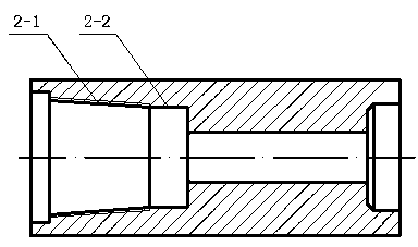
[0026] see figure 1 , the outer diameter of the dual power auger drill pipe φ 1 50mm, rod inner diameter φ 2 It is 34mm, and the length L is 1000mm. It is composed of a male joint 1, a rod body 3, a female joint 2 and a helical blade 4 connected in sequence, and is welded into one body by friction welding. The male joint 1 is connected to the next drill pipe female joint 2 The connection end of the drill pipe joint 1 is composed of the straight shaft section 1-2 and the external taper thread 1-1 in turn; Threaded 2-1 connection composition. The thread type of the external tapered thread 1-1 of the male joint and the internal tapered thread 2-1 of the female joint is a positive spiral tapered thread, the taper is 1:8, and the pitch is 5.08mm (5 teeth per inch). The straight shaft section 1-2 of the male joint is pro...


PUM


Abstract

The invention relates to an auger stem which is used for drilling operation and hydraulic seam cutting in a soft coal seam, in particular to a high-pressure water seal dual power auger stem. A high-pressure water seal dual power auger stem body is formed by sequential connection of a male connector, a rod body and a female connector in a welding mode, and helical blades are welded on the periphery of the male connector, the rod body and the female connector. Dual-power combination of fluid slag discharge (wind power slag discharge or waterpower slag discharge) and mechanical slag discharge are used in the auger stem, the section of each helical blade is in a shape of a pentagon which is formed by the fact that one right angle of a rectangle is chamfered, grinding effect on coal particles of big size can be achieved when a hole is drilled, a sealing ring placed on a straight shaft section of the male connector is closely contacted with an shaft surface of a straight shaft hole section of the female connector of a next auger stem, and accordingly radial seal is achieved, high pressure water of 50 MPa can be borne due to combined action with a tightened taper thread, and leakage is avoided. The high-pressure water seal dual power auger stem is reasonable in design, simple in structure, easy to process, low in cost, safe and reliable, good in slag discharge effect, deep in drilling depth and high in working efficiency.

Description

technical field [0001] The invention relates to a drill pipe used in drilling operations and hydraulic slotting in weak coal seams, in particular to a high-pressure water-sealed dual-power auger drill pipe. Background technique [0002] The existing common auger pipe has thick and narrow helical blades. Although it has a good slagging effect during drilling construction, the auger pipe has a large rotation resistance and is prone to breakage of the drill pipe. It is only suitable for relatively simple formations. , and the twisting and unscrewing of the auger drill pipe is more troublesome. Usually, it can only be unscrewed manually, and it is difficult to unscrew it with a quick unscrewing device, so that the construction efficiency is low, and the material and labor input are large. [0003] The use of high-pressure hydraulic slotting to drill deep holes and slots in low-permeability coal can increase the free surface of coal seam gas gushing out, promote rapid pressure re...

Claims


Application Information

Patent Timeline
Patent Type & Authority Applications(China)
IPC IPC(8): E21B17/22E21B17/042
Inventor 夏彬伟卢义玉杜鹏汤积仁胡科葛兆龙刘承伟赵彬钦
Owner CHONGQING UNIV
Why Eureka
Try Eureka