Soot blowing method of heating furnace

A technology of heating furnace and soot blower, which is applied in the field of heating furnace soot blowing, and can solve problems such as failure to blow, under-blowing, blindness of soot blowing operation, etc.

Inactive Publication Date: 2012-12-26
CHINA PETROLEUM & CHEM CORP +1
View PDF5 Cites 9 Cited by
  • Summary
  • Abstract
  • Description
  • Claims
  • Application Information

AI Technical Summary

Problems solved by technology

[0004] The purpose of the present invention is to provide a heating furnace soot blowing method for heating furnaces in petroleum refining and petrochemical fields, which is used to solve the problem that the existing soot blowing method c...

Method used


Image

  • Soot blowing method of heating furnace

Examples


Embodiment Construction

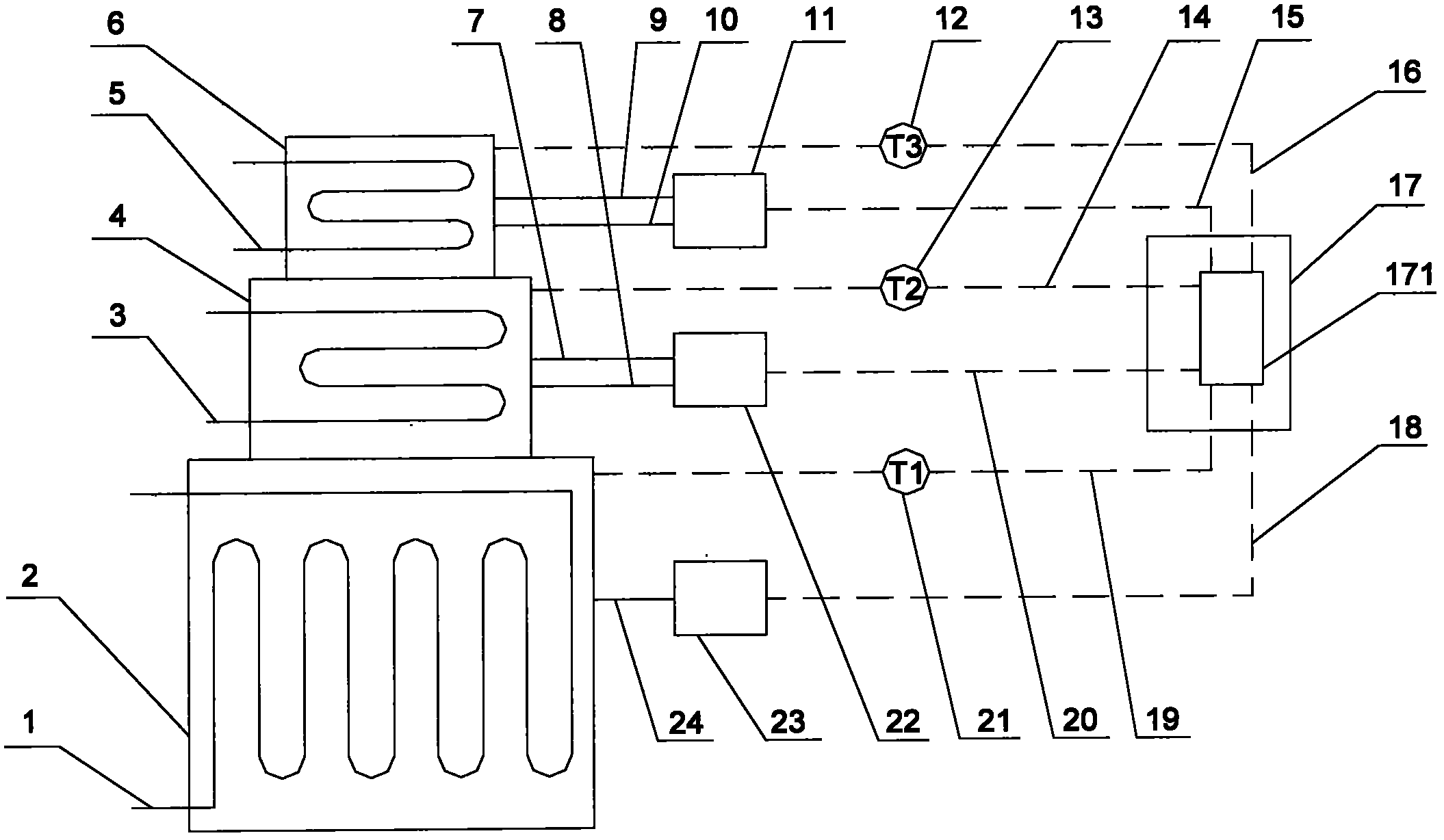
[0019] figure 1 The present invention is applied to a tubular heating furnace. This type of tubular heating furnace is currently the most widely used in refining and chemical enterprises. It includes three parts: radiation section 2, convection section 4 and air preheater 6. The radiation furnace tube 1 is set in the section 2, the convection furnace tube 3 is set in the convection section 4, and the heat exchange tube 5 is set in the air preheater 6. The radiation furnace tube 1 can only be cleaned with a soot cleaning agent due to structural reasons, and the convection furnace The tube 3 and the heat exchange tube 5 can use a combination of steam and soot cleaning agent cleaning technology.

[0020] Each area of ​​the heating furnace is equipped with a flue gas outlet temperature measuring device: a radiation section temperature measuring device 21 a convection section temperature measuring device 13 and an air preheater section temperature measuring device 12, and the flue ...


PUM


Abstract

The invention discloses a soot blowing method of a heating furnace. The method comprises the following steps: A, outlet flue gas temperature values T1, T2 and T3 of a radiation section, a convection section and an air preheater of the heating furnace are respectively measured by a thermoelectric couple, and are transmitted to a control cabinet; B, the control cabinet compares the outlet flue gas temperature values T1, T2 and T3 with preset outlet flue gas temperature values TC1, TC2 and TC3 of the radiation section, the convection section and the air preheater of the heating furnace which is normally operated, so as to obtain a signal for determining whether the radiation section, the convection section and the air preheater of the heating furnace are required to carry out soot blowing and a signal of soot blowing time according to difference values DeltaT1, DeltaT2 and DeltaT3; C, soot blowing machines of the radiation section, the convection section and the air preheater of the heating furnace accomplish soot blowing operation according to a soot blowing signal of the control cabinet; and D, steps A, B and C are repeated. The soot blowing method can perform blowing operation according to the practical soot accumulated state on the surface of a furnace tube or a heat exchange tube and perform timed and designated area blowing, and the phenomenon of over-blowing or under-blowing can not occur.

Description

technical field [0001] The invention relates to a heating furnace soot blowing method used in heating furnaces in the fields of petroleum refining and petrochemical industry. Background technique [0002] With the change of the nature of crude oil and the increase of sulfur content, the problem of fouling and fouling on the heating surfaces of heating furnace radiation section furnace tubes, convection section furnace tubes and air preheater heat exchange tubes in domestic petrochemical enterprises is becoming more and more serious. Once the heating surface Dust accumulation will seriously affect the heat transfer effect of the heating surface. In the case of severe ash on the surface of the furnace tube in the convection section, the heat transfer capacity will be reduced by about 30% to 50%, which will reduce the thermal efficiency of the heating furnace by more than 5%, and the fuel energy consumption of the heating furnace accounts for 30% of the total energy consumption...

Claims


Application Information

Patent Timeline
IPC IPC(8): F23J1/00F23J3/02
Inventor 郜建松孙志钦孟庆凯
Owner CHINA PETROLEUM & CHEM CORP
Why Eureka
Try Eureka