
Vacuum tube wall type heat absorber

A vacuum tube and heat sink technology, which is applied to heating devices, solar thermal devices, solar thermal power generation, etc., can solve the problems of high concentrating precision requirements of heliostat field, prone to high temperature oxidation, small opening of heat sink, etc. Achieve the effect of improving energy utilization efficiency, simple structure and increasing opening area

Inactive Publication Date: 2012-12-26
INST OF ELECTRICAL ENG CHINESE ACAD OF SCI
View PDF11 Cites 1 Cited by
  • Summary
  • Abstract
  • Description
  • Claims
  • Application Information

AI Technical Summary

Problems solved by technology

[0004] The purpose of the present invention is to overcome the shortcomings of the heat absorber of the existing tower type solar thermal power generation system, such as the low heat absorption efficiency at high temperature, the high requirement for the concentration precision of the heliostat field, the small opening of the heat absorber, etc. Due to the disadvantages of high temperature oxidation, easy aging and short service life, a vacuum tube wall heat absorber is proposed

Method used


Image

  • Vacuum tube wall type heat absorber
  • Vacuum tube wall type heat absorber
  • Vacuum tube wall type heat absorber

Examples


Embodiment Construction

[0031] The present invention will be further described below in conjunction with the accompanying drawings and specific embodiments.

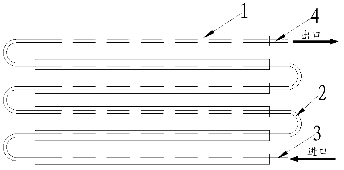
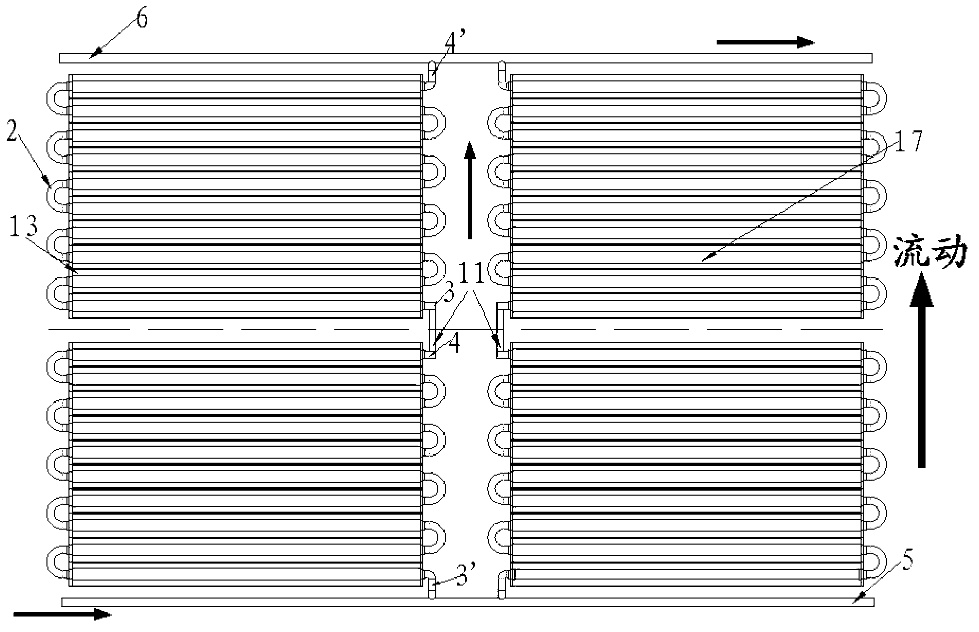
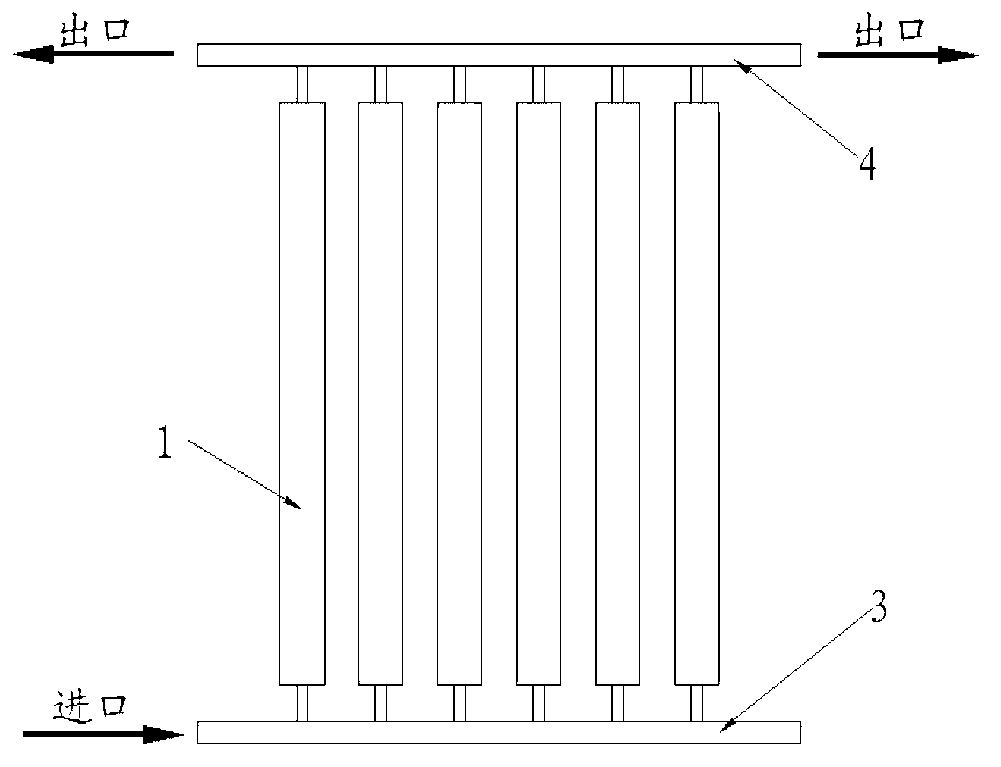
[0032] The vacuum tube wall heat absorber of the present invention is composed of series heat absorption modules 17 or parallel heat absorption modules 18 , connecting pipes 11 , inlet main pipe 5 and outlet main pipe 6 .

[0033] A plurality of the heat-absorbing modules 17, 18 are connected in series through the connecting pipeline 11, one end of the connecting pipeline 11 is welded to the inlet pipe 3 of the heat-absorbing module, and the other end of the connecting pipeline 11 is connected to the outlet pipe of the heat-absorbing module. 4 welding Unicom. The inlet main pipe 5 is the main pipeline through which the heat transfer working medium of the heat absorber flows into the heat absorber, and the inlet main pipe 5 and the heat absorption module inlet pipes 3' of the heat absorption modules 17 and 18 located at the outermost side of the...


PUM


Abstract

The invention relates to vacuum tube wall type heat absorber. Straight-through vacuum tubes (1) are connected in series or parallel by U-shaped connection tubes (2) to form a single series heat absorbing module (17) or single parallel heat absorbing module (18). A plurality of series heat absorbing modules (17) or parallel heat absorbing modules (18) are connected in series or parallel by connecting tubes (11) to form the vacuum tube wall type heat absorber. The vacuum tube wall type heat absorber is in a two-dimensional curved surface or external cylinder or plane shape. The straight-through vacuum tubes (1) are arranged horizontally, vertically relative to the ground, slantwise or juxtaposedly in multiple rows. The vacuum tube wall type heat absorber is arranged on the top of a heat absorbing tower (7) unidirectionally or circumferentially. The back surfaces of the straight-through vacuum tubes (1) can be provided with compound parabolic concentrators (CPC) or plane or hemispherical secondary condensers (13).

Description

technical field [0001] The invention relates to a solar high temperature heat absorber. Background technique [0002] The basic principle of tower solar thermal power generation is to use many heliostats to reflect solar radiation to the surface of the heat absorber placed on the upper part of the heat absorption tower, and use the steam or high-temperature air generated by the heating medium to drive the generator set to generate electricity . Since the 1980s, tower-type solar thermal power generation technology has developed rapidly, and a number of tower-type solar test power stations have been put into trial operation. A large number of experiments and operating data prove that the tower solar thermal power generation technology has the outstanding advantages of high temperature, high concentration ratio and high power generation efficiency, and has great prospects and competitiveness in the process of commercialization. [0003] The heat absorber is one of the core co...

Claims


Application Information

Patent Timeline
Patent Type & Authority Applications(China)
IPC IPC(8): F24J2/46
CPCY02E10/40
Inventor 王志峰张鸿斐雷东强白凤武李鑫
Owner INST OF ELECTRICAL ENG CHINESE ACAD OF SCI
Learn More