
Novel high temperature smoke fluidized bed furnace

A high-temperature flue gas, boiling furnace technology, used in air heaters, heating devices, dryers, etc., can solve the problems of inability to completely remove sediment and scum, disturbance of airflow and heat flow, and easy collapse of the fire wall. Guaranteed drying and heat transfer, reduced mass, and simple structure

Inactive Publication Date: 2012-12-26
张斌
View PDF0 Cites 1 Cited by
  • Summary
  • Abstract
  • Description
  • Claims
  • Application Information

AI Technical Summary

Problems solved by technology

[0004] The fluidized fluidized furnace can not only burn high-quality coal, but also can burn all kinds of low-quality coal that cannot be burned in general grate furnaces and chamber furnaces; the heat transfer effect in the bed is very good, and the generation of nitrogen oxides in the flue gas is small, but the existing fluidized Structural defects make the heat flow slow during use, easy to coke, and the fire-retaining wall is easy to collapse, and the service life is short. At the same time, the sediment and scum in the furnace cannot be completely removed, which greatly affects the exhaust of the air outlet. Cloth, the boiling condition is not good, which affects the output of heat flow, and the setting of overflow slag outlet and coal inlet changes the structure of the furnace, which also has a disturbing effect on air flow and heat flow

Method used


Image

  • Novel high temperature smoke fluidized bed furnace

Examples


Embodiment Construction

[0019] The present invention will be further explained and illustrated below in conjunction with the accompanying drawings.

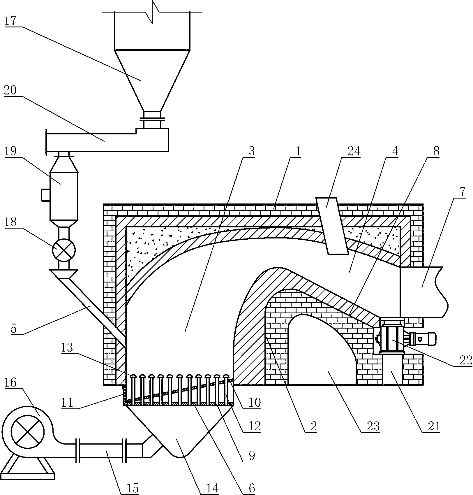
[0020] A novel high-temperature fluidized fluidized furnace of the present invention, as shown in the accompanying drawings, comprises a furnace body 1, a fire-retaining wall 2 arranged in the furnace body 1, a combustion chamber 3 and a mixing chamber 4 bounded by the fire-retaining wall 2 in the furnace body 1 ; The side wall of the body of furnace 1 of the combustion chamber 3 is inclined to be provided with a coal inlet pipe 5, and the bottom is provided with an air distribution plate 6; the side wall of the body of furnace 1 of the mixing chamber 4 is provided with an air outlet 7; wherein, the top of the body of furnace 1 is The upwardly protruding arc is conducive to the flow of hot air without forming a dead angle and avoiding coking; the fire wall 2 is located on one side of the combustion chamber 3, and the lower part is vertical, and the upper...


PUM


Abstract

The invention relates to a fluidized bed furnace for drying in the industry, in particular to a novel high temperature smoke fluidized bed furnace which is thorough in slag discharging and long in service life, and a coking phenomenon cannot happen. The novel high temperature smoke fluidized bed furnace comprises a furnace body (1), a fire blocking wall (2) is arranged inside the furnace body, the inside of the furnace body (1) is separated by the fire blocking wall (1) into a combustion chamber (3) and a mixing chamber (4). A coal inlet pipe (5) is arranged on the lateral wall of the furnace body (1) of the combustion chamber (3) in inclination mode, a wind distribution plate (6) is arranged at the bottom of the furnace body (1), and an air outlet (7) is arranged on the lateral wall of the furnace body (1) of the mixing chamber (4). The novel high temperature smoke fluidized bed furnace is characterized in that the top of the furnace body (1) is in an arc shape protruding upwards, the fire blocking wall (2) is vertically located at the lower portion of one side of the mixing chamber (4), and the upper portion is in an arc shape curving to the mixing chamber (4). The fire blocking wall (2) is located on one side of the mixing chamber (4) to be connected with the bottom of the mixing chamber (4) to form an inclined face (8) with the same inclination, and the tail end of the inclined face (8) is connected with the bottom end of the air outlet (7).

Description

technical field [0001] The invention relates to an industrial drying fluidized furnace, in particular to a novel high-temperature flue gas fluidized furnace. Background technique [0002] The fluidized bed is based on the fluidization technology. Under the action of the air flow, the solid particles form a fluidized bed that seems to be in a boiling state, which is called a fluidized bed or a fluidized bed. The solid material fluidization technology was proposed by Winkler in Germany in 1921, and it was first used in the chemical and metallurgical industries. Since the 1950s, it has been transplanted to the combustion field of boilers and has been developed. The solid fuel is held up by the upward flow of air in the furnace, rolls up and down within a certain height range, and burns in a fluidized (or boiling) state, so the fluidized bed furnace is also called a fluidized bed combustion furnace. [0003] Fluidized fluidized furnace is to blow the coal dust broken to a cert...

Claims


Application Information

Patent Timeline
Patent Type & Authority Applications(China)
IPC IPC(8): F26B23/02F24H3/00
Inventor 张斌
Owner 张斌
Learn More