Iterative FFT-based quick MIMO radar waveform synthesis method

A waveform synthesis and radar echo technology, applied in the field of radar, can solve the problems of not considering the spatial synthesis signal or the relevant characteristics of the echo signal, and unable to meet the requirements of online design waveform engineering.

Active Publication Date: 2012-12-26
XIDIAN UNIV
View PDF4 Cites 15 Cited by
  • Summary
  • Abstract
  • Description
  • Claims
  • Application Information

AI Technical Summary

Problems solved by technology

However, the above-mentioned existing waveform design methods neither consider the relevant characteristics of the spatially synthesized signal or the echo signal, nor can they meet the engineering requirements of online waveform design.

Method used


Image

  • Iterative FFT-based quick MIMO radar waveform synthesis method
  • Iterative FFT-based quick MIMO radar waveform synthesis method
  • Iterative FFT-based quick MIMO radar waveform synthesis method

Examples


Embodiment Construction

[0052] refer to figure 1 , the specific implementation steps of this embodiment are as follows:

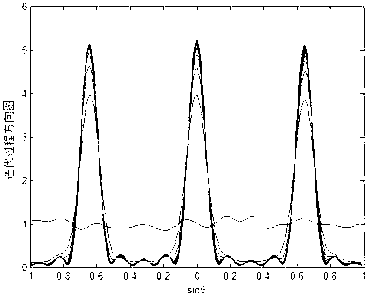
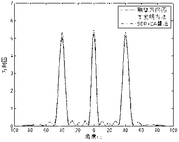
[0053] Step 1, set the desired pattern and determine the sampling points in the airspace.

[0054] Assuming that the MIMO radar array is a uniform linear array composed of M array elements, the constant modulus waveform matrix is ​​defined as

[0055] X=[x 1 ,x 2 ,...x L ] T ,

[0056] where x l =[x l,1 ,...,x l,M ] T is the transpose of the lth row of X, representing the lth sub-pulse signal, where |x l,m |=1,x l,m is the element of row l and column m of waveform X, l=1,...,L, m=1,...,M, (·) T Indicates the transposition, |·| indicates the modulus value of the complex number, and L indicates the code length, then the emission pattern of the constant modulus waveform matrix X can be expressed as

[0057] P(θ)=a H (θ)X H Xa(θ) / L,

[0058] where a(θ)=[1,...,e j2πdsinθ / λ ] T Indicates the steering vector, θ indicates the azimuth angle, d indicates the array element...


PUM


Abstract

The invention discloses an iterative FFT (Fast Fourier Transform)-based quick MIMO (Multiple Input Multiple Output) radar waveform synthesis method, and aims to solve the problems that a current method, which can not quickly synthesize the waveform meeting empty domain and time domain property. The realization process comprises the following steps: setting an expected emission directional pattern of a radar according to the objective information of a radar return, and determining a discrete azimuth angle based on the inverse Fourier transform relation of the emission directional pattern with a waveform matrix; obtaining a constant modulus waveform matrix of the radar in a way that an iterative FFT manner is adopted to synthesize the directional patterns according to the expected emission directional pattern; utilizing the constant modulus waveform matrix to construct a phase shift constant modulus waveform matrix; and utilizing the iterative manner to optimize sub pulse initial phase of the phase shift constant modulus waveform matrix so as to improve the signal self-correlation property in the objective direction, and finally obtaining the synthetic waveform. According to the invention, the method realizes on-line waveform design and can be used for multi-objective tracking of the MIMO radar.

Description

technical field [0001] The invention belongs to the technical field of radar and relates to the synthesis of radar waveforms, which can be used in the online waveform design of MIMO radars to meet engineering requirements. Background technique [0002] Multiple-input multiple-output MIMO radar is a new active detection technology, and has become a research hotspot in the field of radar technology. [0003] In 2003, Rabideau and Parker proposed the concept of MIMO radar by referring to MIMO technology and SIAR in the communication field, see [Rabideau D.J.and Parker P..Ubiquitous MIMO Multifunction Digital Array Radar[C].Conference Record of the 37th Asilomar Conference on Signals, Systems and Computers, 2003, vol.1, pp.1057-1064]. Afterwards, this concept attracted a lot of attention in the radar field. At present, MIMO radars can be classified into distributed MIMO radars and centralized MIMO radars according to the distance between antennas. For distributed MIMO radar, ...

Claims


Application Information

Patent Timeline
Patent Type & Authority Applications(China)
IPC IPC(8): G01S7/28
Inventor 刘宏伟王旭戴奉周纠博周生华
Owner XIDIAN UNIV
Why Eureka
Try Eureka