Halogen lamp foot-bending machine

A technology of bending machine and halogen lamp, which is applied in the direction of electrical components, etc., can solve problems such as unsatisfactory, broken lamp legs, disordered direction of lamp legs, etc., and achieves the effect of beautiful appearance and high yield

Active Publication Date: 2012-12-26
佛山新曜阳智能科技有限公司
View PDF5 Cites 8 Cited by
  • Summary
  • Abstract
  • Description
  • Claims
  • Application Information

AI Technical Summary

Problems solved by technology

[0002] In the process of bending the halogen lamp, generally the bending process is carried out directly after the lamp pin is straightened. Due to the lack of pre-bending process, the lamp pin does not have a bending pin guide before bending, so the lamp pin often appears. The direction of the feet is wrong or the light feet that come out of the bent feet are mixed and varied, which cannot meet the requirements of industrialization and standardized production, and even the lamp feet may be broken.

Method used


Image

  • Halogen lamp foot-bending machine
  • Halogen lamp foot-bending machine
  • Halogen lamp foot-bending machine

Examples


Embodiment Construction

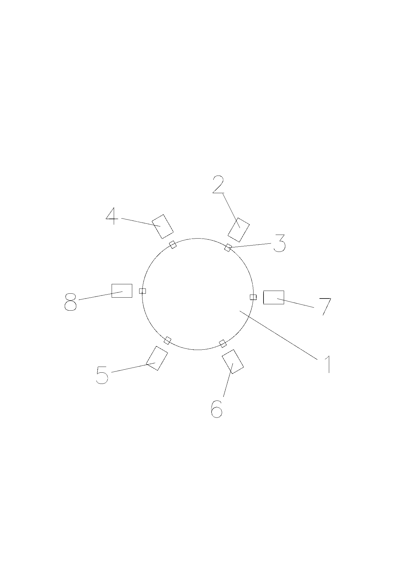
[0020] refer to Figure 1~5 , a halogen lamp bending machine, including a working platform, the center of the working platform is provided with a multi-station turntable 1, the multi-station turntable 1 is installed on an arc cam divider, and the multi-station turntable 1 is Each station in the radial direction is provided with a bulb fixture 3, and the outer side of the bulb fixture 3 is sequentially provided with a vibrating plate feeding mechanism 2, a lamp leg straightening mechanism 4, a leg bending mechanism 5, and a lamp leg shaping mechanism. mechanism 6 and blanking mechanism 7, a pre-bending mechanism 8 is provided between the lamp pin straightening mechanism 4 and the bending mechanism 5; by adding the pre-bending mechanism 8, the lamp pin is pre-bent before bending Bend to make it form a certain pre-bending angle, which can be more convenient for the subsequent bending work and improve the yield.

[0021] In order to facilitate the positioning of the bulb, the bul...


PUM


Abstract

The invention discloses a halogen lamp foot-bending machine comprising a work platform. A multi-station rotary plate is arranged in the center of the work platform. A bulb clamping device is arranged on each station along the radial direction of the multi-station rotary plate. A vibrating plate feeding mechanism, a lamp foot straightening mechanism, a foot-bending mechanism, a lamp foot reshaping mechanism and a blanking mechanism are arranged in sequence outside each bulb clamping device along the circumferential direction. A foot pre-bending mechanism is arranged between the lamp foot straightening mechanism and the foot-bending mechanism. As the foot pre-bending mechanism is arranged between the lamp foot straightening mechanism and the foot-bending mechanism, lamp feet are bent to a certain position in advance so that during a process bending the feet, foot-bending process of the lamp feet can be finished according to the former pre-bending position, and yield of the bent feet is greatly improved. The lamp foot reshaping mechanism enables appearance of the lamp feet to be attractive, so practical requirements of the lamp feet are met and industrialized and standardized production is achieved.

Description

technical field [0001] The invention relates to a light bulb processing machine, in particular to a halogen lamp bending machine with good bending effect. Background technique [0002] In the process of bending the halogen lamp, generally, the bending process is carried out directly after the lamp pin is straightened. Due to the lack of pre-bending process, the lamp pin does not have a bending pin guide before bending, so the bending of the lamp pin often occurs. The direction of the feet is wrong or the lamp feet that come out of the bent feet are mixed and varied, which cannot meet the requirements of industrialization and standardized production, and even the lamp feet may break. Contents of the invention [0003] In order to overcome the deficiencies of the prior art, the invention provides a halogen lamp bending machine. [0004] The technical solution adopted by the present invention to solve its technical problems is: [0005] A halogen lamp bending machine, inclu...

Claims


Application Information

Patent Timeline
Patent Type & Authority Applications(China)
IPC IPC(8): H01K3/00
Inventor 李洪普
Owner 佛山新曜阳智能科技有限公司
Why Eureka
Try Eureka