Screw-thread-driven rotary-linear ultrasonic motor using columnar stator high-order bending vibration mode

A linear ultrasonic motor, bending vibration technology, applied in the direction of generator/motor, piezoelectric effect/electrostrictive or magnetostrictive motor, electrical components, etc., can solve the problem of small output torque, achieve performance improvement, work High efficiency and good mechanical properties

Active Publication Date: 2012-12-26
HARBIN INST OF TECH
View PDF4 Cites 35 Cited by
  • Summary
  • Abstract
  • Description
  • Claims
  • Application Information

AI Technical Summary

Problems solved by technology

[0006] The present invention aims to solve the problem of small output torque when the thread-driven rotary-linear ultrasonic motor in the bending vibration mode of t...

Method used


Image

  • Screw-thread-driven rotary-linear ultrasonic motor using columnar stator high-order bending vibration mode
  • Screw-thread-driven rotary-linear ultrasonic motor using columnar stator high-order bending vibration mode
  • Screw-thread-driven rotary-linear ultrasonic motor using columnar stator high-order bending vibration mode

Examples


specific Embodiment approach 1

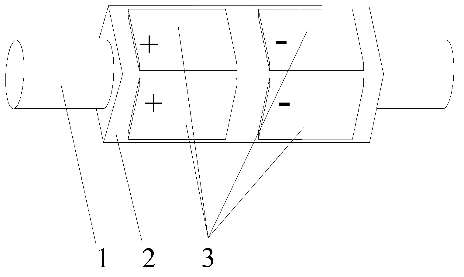
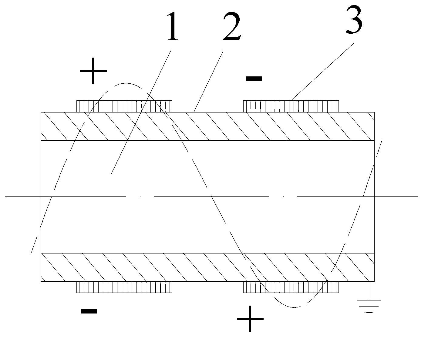
[0053] Specific implementation mode one: the following combination Figure 1 to Figure 7 This embodiment is described. The thread-driven rotary linear ultrasonic motor using the high-order bending vibration mode of the cylindrical stator described in this embodiment includes a threaded output shaft 1, a metal tube elastic sleeve 2 and m groups of piezoelectric ceramic sheets 3, m is a positive integer,

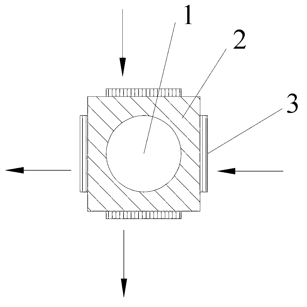
[0054] The metal tube elastic sleeve 2 is sleeved on the outer surface of the threaded output shaft 1, and is connected with the threaded output shaft 1 through a thread pair. The outer contour of the cross section of the metal tube elastic sleeve 2 is a regular n-gon, and the value of n is is an integer multiple of 4,

[0055] On the outer surface of the metal tube elastic sleeve 2, m groups of piezoelectric ceramic sheets 3 are evenly distributed in the axial direction, each group of piezoelectric ceramic sheets 3 is composed of n piezoelectric ceramic sheets, and each grou...

specific Embodiment approach 2

[0061] Specific implementation mode two: the following combination Figure 8 to Figure 12 This embodiment is described. The thread-driven rotary linear ultrasonic motor using the high-order bending vibration mode of the cylindrical stator described in this embodiment includes a threaded output shaft 1, a metal tube elastic sleeve 2 and m groups of piezoelectric ceramic sheets 3, m is a positive integer,

[0062] The metal tube elastic sleeve 2 is sleeved on the outer surface of the threaded output shaft 1, and is connected with the threaded output shaft 1 through a thread pair. The outer contour of the cross section of the metal tube elastic sleeve 2 is composed of a circular arc and two straight lines. A shape composed of arcs greater than or equal to one-half of the circumference, and two straight line segments of equal length and perpendicular to each other;

[0063] On the outer surface of the metal tube elastic sleeve 2, m groups of piezoelectric ceramic sheets 3 are eve...

specific Embodiment approach 3

[0071] Specific implementation mode three: the following combination figure 2 and Image 6 This embodiment is described. This embodiment is a further description of Embodiment 1 or 2. The m groups of piezoelectric ceramic sheets 3 are respectively located at the center amplitudes of m amplitudes of the m-order bending vibration of the metal tube elastic sleeve 2 .


PUM


Abstract

The invention discloses a screw-thread-driven rotary-linear ultrasonic motor using a columnar stator high-order bending vibration mode, which belongs to the technical field of ultrasonic motors and is used for solving the problem of small output torque during miniaturization of a screw-thread-driven rotary-linear ultrasonic motor using the columnar stator high-order bending vibration mode. The screw-thread-driven rotary-linear ultrasonic motor comprises a screw thread output shaft, a metal tube elastic sleeve and m groups of piezoelectric ceramic sheets, or comprises a screw thread output shaft, a piezoelectric ceramic tube, two metal caps and p groups of outer electrodes. Two mutually orthogonal high-order bending vibrations such as two-order or three-order bending vibration modes on a free stator space are excited, driving travelling waves are generated on the inner surface of a stator driving end consisting of the metal tube elastic sleeve and the m groups of piezoelectric ceramic sheets by laminating and coupling the vibrations, and a stator and the screw thread output shaft are driven through a screw thread pair, so that rotary-linear motion output of the output shaft is realized under the action of axial loading force. The screw-thread-driven rotary-linear ultrasonic motor is taken as a rotary-linear ultrasonic motor.

Description

technical field [0001] The invention relates to a thread-driven rotary linear ultrasonic motor utilizing the high-order bending vibration mode of a columnar stator, and belongs to the technical field of ultrasonic motors. Background technique [0002] The thread-driven rotary-linear ultrasonic motor using the bending vibration mode of the cylindrical stator is one of many types of ultrasonic motors. Compared with other types of ultrasonic motors, the stator and output shaft of this type of ultrasonic motor are The two spatially orthogonal bending vibration modes use the coupling and superposition of vibration to generate driving traveling waves on the inner surface of the stator driving end, which can easily realize the output of the screw output shaft rotation-linear degree of freedom motion. Compared with the disc traveling wave ultrasonic motor, it has the characteristics of simple structure, easy miniaturization and high positioning accuracy. [0003] The thread-driven ...

Claims


Application Information

Patent Timeline
IPC IPC(8): H02N2/00
Inventor 包钢程廷海高焓郭向东肖承丰王维张宏宇
Owner HARBIN INST OF TECH
Why Eureka
Try Eureka