Screw-thread-driven rotary-linear ultrasonic motor using columnar stator high-order bending vibration mode
A linear ultrasonic motor, bending vibration technology, applied in the direction of generator/motor, piezoelectric effect/electrostrictive or magnetostrictive motor, electrical components, etc., can solve the problem of small output torque, achieve performance improvement, work The effect of high efficiency and broad application prospects
- Summary
- Abstract
- Description
- Claims
- Application Information
AI Technical Summary
Problems solved by technology
Method used
Image
Examples
specific Embodiment approach 1
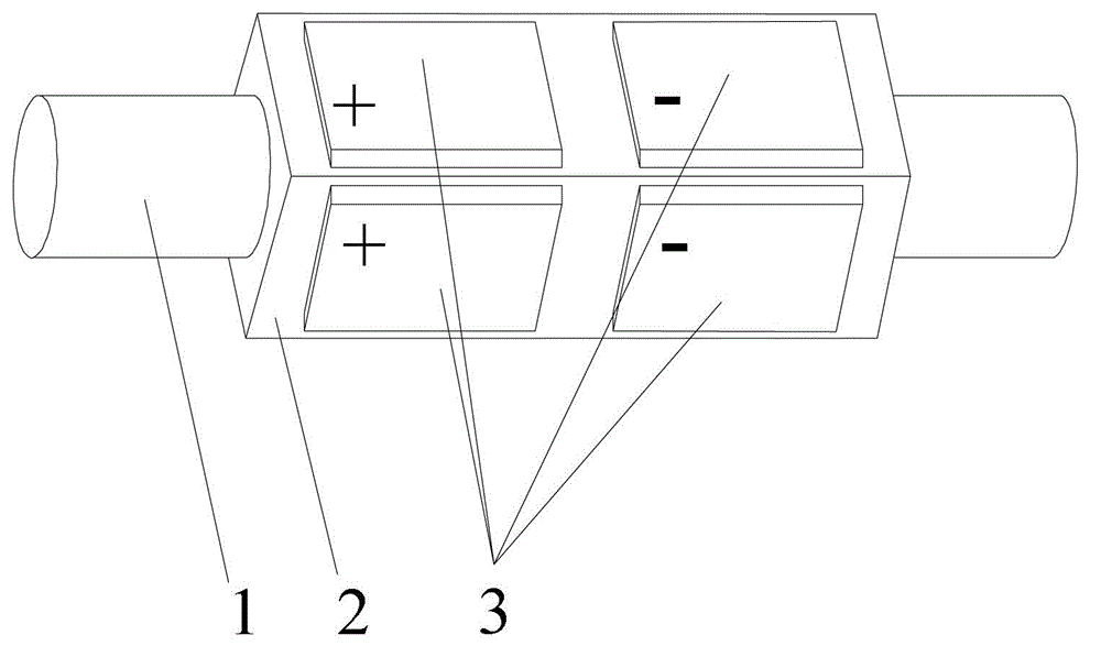
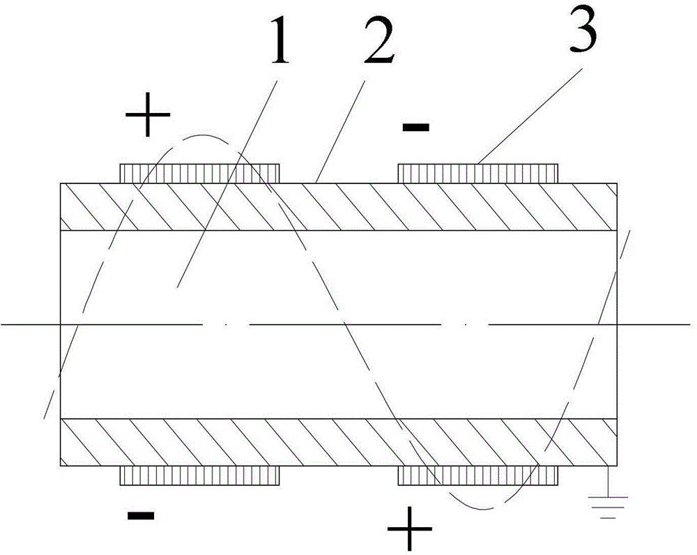
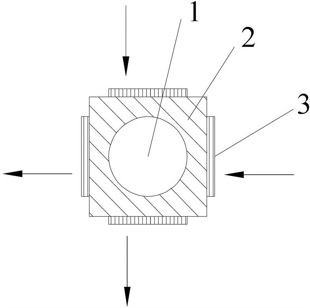
[0053] Specific implementation mode 1: the following combination Figure 1 to Figure 7 To explain this embodiment, the thread-driven rotary linear ultrasonic motor using the cylindrical stator high-order bending vibration mode described in this embodiment includes a threaded output shaft 1, a metal tube elastic sleeve 2 and m groups of piezoelectric ceramic sheets 3. m is a positive integer,
[0054] The metal tube elastic sleeve 2 is sleeved on the outer surface of the threaded output shaft 1, and is connected with the threaded output shaft 1 through a thread pair. The outer contour of the cross section of the metal tube elastic sleeve 2 is a regular n-sided shape, the value of n Is an integer multiple of 4,
[0055] On the outer surface of the metal tube elastic sleeve 2, m groups of piezoelectric ceramic plates 3 are uniformly distributed along the axial direction. Each group of piezoelectric ceramic plates 3 is composed of n piezoelectric ceramic plates. Each group of piezoelec...
specific Embodiment approach 2
[0061] Specific implementation manner 2: the following combination Figure 8 to Figure 12 To illustrate this embodiment, the thread-driven rotary linear ultrasonic motor using the cylindrical stator high-order bending vibration mode in this embodiment includes a threaded output shaft 1, a metal tube elastic sleeve 2 and m groups of piezoelectric ceramic sheets 3. m is a positive integer,
[0062] The metal tube elastic sleeve 2 is sleeved on the outer surface of the threaded output shaft 1, and is connected with the threaded output shaft 1 through a thread pair. The outer contour of the cross section of the metal tube elastic sleeve 2 is composed of a circular arc and two straight sections The shape of the composition, where the arc is greater than or equal to one-half of the circumference, and the two straight lines are equal in length and perpendicular to each other;
[0063] On the outer surface of the metal tube elastic sleeve 2, m groups of piezoelectric ceramic plates 3 are e...
specific Embodiment approach 3
[0071] Specific implementation manner three: the following combination figure 2 with Image 6 To illustrate this embodiment, this embodiment is a further description of the first or second embodiment. The m groups of piezoelectric ceramic sheets 3 are respectively located at the center amplitudes of m amplitudes of the m-order bending vibration of the metal tube elastic sleeve 2.
PUM
 Abstract
Description
Claims
Application Information
 - R&D
- Intellectual Property
- Life Sciences
- Materials
- Tech Scout
- Unparalleled Data Quality
- Higher Quality Content
- 60% Fewer Hallucinations
Browse by: Latest US Patents, China's latest patents, Technical Efficacy Thesaurus, Application Domain, Technology Topic, Popular Technical Reports.
© 2025 PatSnap. All rights reserved.Legal|Privacy policy|Modern Slavery Act Transparency Statement|Sitemap|About US| Contact US: help@patsnap.com


