Distance measuring device having homogenizing measurement evaluation

A technology of measuring device and evaluation device, applied in the direction of measuring device, measuring distance, line-of-sight measurement, etc.

Inactive Publication Date: 2012-12-26
ROBERT BOSCH GMBH
View PDF4 Cites 9 Cited by
  • Summary
  • Abstract
  • Description
  • Claims
  • Application Information

AI Technical Summary

Problems solved by technology

[0007] It has been observed that measuring devices (which work for example on the basis of at least one photosensitive detector, a multiplexer layout and a hierarchical architecture in the manner described above) do not always provide satisfactory measurement accuracy

Method used


Image

  • Distance measuring device having homogenizing measurement evaluation
  • Distance measuring device having homogenizing measurement evaluation
  • Distance measuring device having homogenizing measurement evaluation

Examples


Embodiment Construction

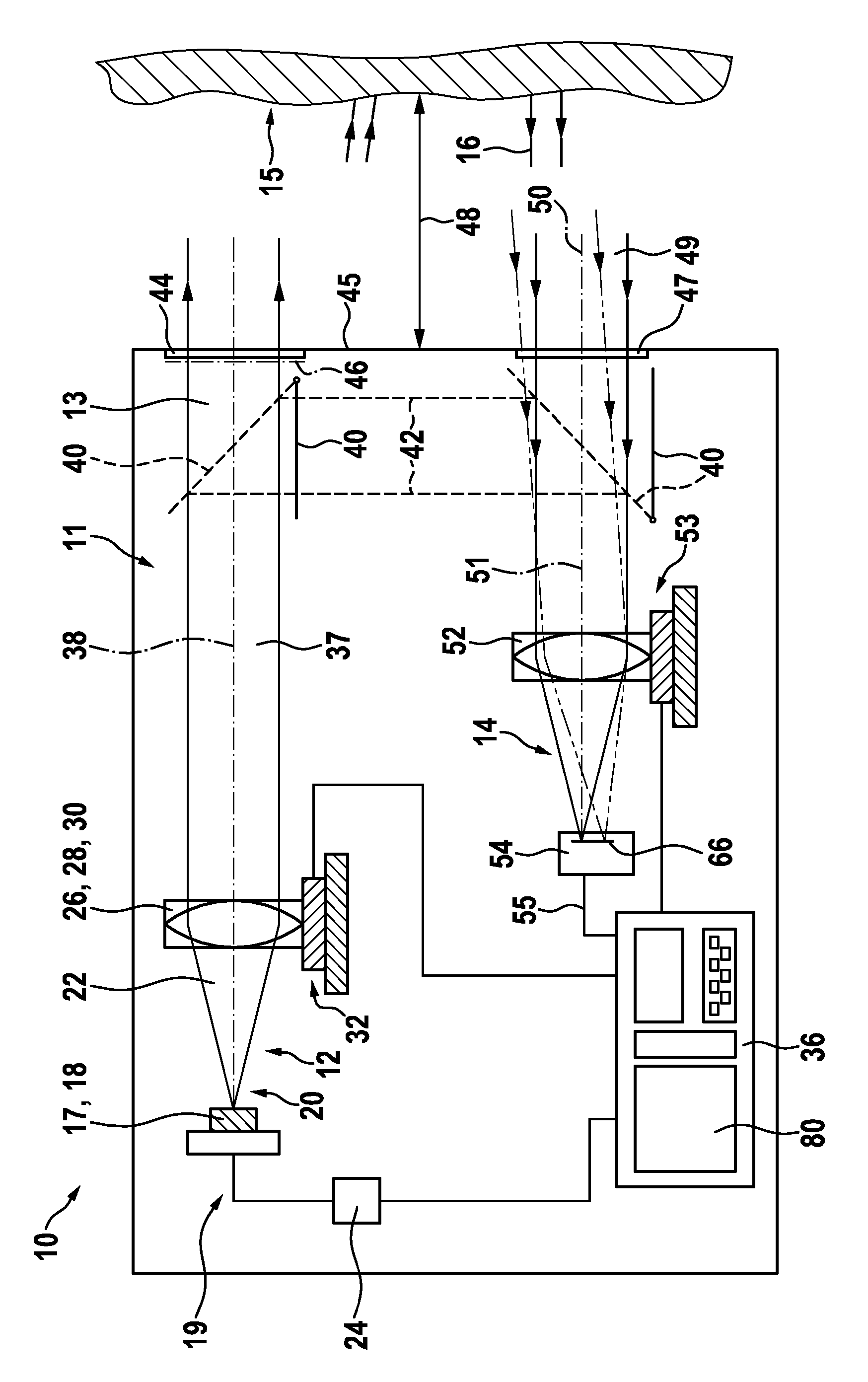
[0031] figure 1 The measuring device 10 according to the invention is shown schematically in the form of an optical distance measuring device with the most important components in order to describe its function. The invention itself is not limited to the scope of optical distance measurement.

[0032] The measuring device 10 has a housing 11 in which a transmitter device 12 for emitting optical measurement radiation 13 and a receiver device 14 for detecting measurement radiation 16 returning from a target object 15 are accommodated.

[0033] The emission device 12 includes a light source, which in the embodiment shown is realized by a semiconductor laser diode 18 . The laser diode 18 emits a laser light 20 in the form of a light beam 22 visible to the naked eye. The laser diode 18 is operated here by a controller 24 , which generates a temporal modulation of the electrical input signal 19 of the laser diode 18 by means of a corresponding electron. Such a modulation of the d...


PUM


Abstract

The invention relates to a measuring device for distance measurement, in particular for optical distance measurement and, for this purpose, a specific way of evaluating detection signals. In a design according to the invention, during various partial measurements (A), (B), (C) a transmitted signal (103) is emitted in the direction of a target object, is reflected there and detected by a receiving device, which, for example, can be designed as a photon counter in the form of a SPAD (single photon avalanche diode). The phase of the transmitted signal (103) is shifted successively in relation to an unshifted signal (101) during the individual partial measurements (A), (B), (C). During sampling time windows (115, 125, 135), the detection signals are fed to associated counters (117, 127, 137). An associated of the counters (117, 127, 137) with the sampling windows (115, 125, 135) can vary between individual the partial measurements (A), (B), (C). In this way, it is possible for background light to be distributed homogeneously over all the counters (119, 127, 137), whereas the transmitted signal (103) is accumulated only in specific counters (117). Measurement errors on account of unequal time spans of the sampling time windows or on account of different measuring sensitivities within various sampling time windows can thus be minimized. Said function is performed by the homogenizing device (80) according to the invention.

Description

technical field [0001] The invention relates to a distance measuring device, in particular to a distance measuring device for optical distance measuring. Background technique [0002] Several optical distance measuring devices are known which direct a time-modulated beam of light at an object whose distance relative to the measuring device is to be determined. The light returned from the aiming object is at least partially detected by the measuring device and used to determine the distance to be measured. A typical distance measurement range here lies between a few centimeters and several hundred meters. [0003] US 2007 / 0182949 A1 discloses a distance measuring device having a light source for illuminating a target using continuously modulated light, a solid-state image sensor with an array of avalanche photodiodes, and multiple sensors for processing the avalanche photodiode emissions. A signal circuit that provides data related to the light reflected from the target to ...

Claims


Application Information

Patent Timeline
Patent Type & Authority Applications(China)
IPC IPC(8): G01S17/36G01S7/4913G01S7/4915
CPCG01S7/4913G01C3/02G01S7/491G01S17/36G01S7/4915G01S17/00
Inventor A.艾泽勒B.施米特克R.施尼策尔
Owner ROBERT BOSCH GMBH
Why Eureka
Try Eureka