Method for manufacturing organic el element and method for setting focal point of laser

一种制造方法、焦点位置的技术,应用在有机半导体器件、半导体/固态器件制造、电气元件等方向,能够解决短寿命、变形或变质、有机EL元件发光效率下降等问题,达到提高利用率、高效率修复的效果

Active Publication Date: 2012-12-26
JAPAN DISPLAY DESIGN & DEV CONTRACT CO LTD
View PDF8 Cites 3 Cited by
  • Summary
  • Abstract
  • Description
  • Claims
  • Application Information

AI Technical Summary

Problems solved by technology

However, if the laser light is also scattered and irradiated to the peripheral part of the short-circuit part, the normal laminated films constituting the organic EL element will be deformed or deteriorated, which will instead lead to a decrease in the luminous efficiency and / or short circuit of the organic EL element. Longevity

Method used


Image

  • Method for manufacturing organic el element and method for setting focal point of laser
  • Method for manufacturing organic el element and method for setting focal point of laser
  • Method for manufacturing organic el element and method for setting focal point of laser

Examples


Embodiment approach 1

[0065]

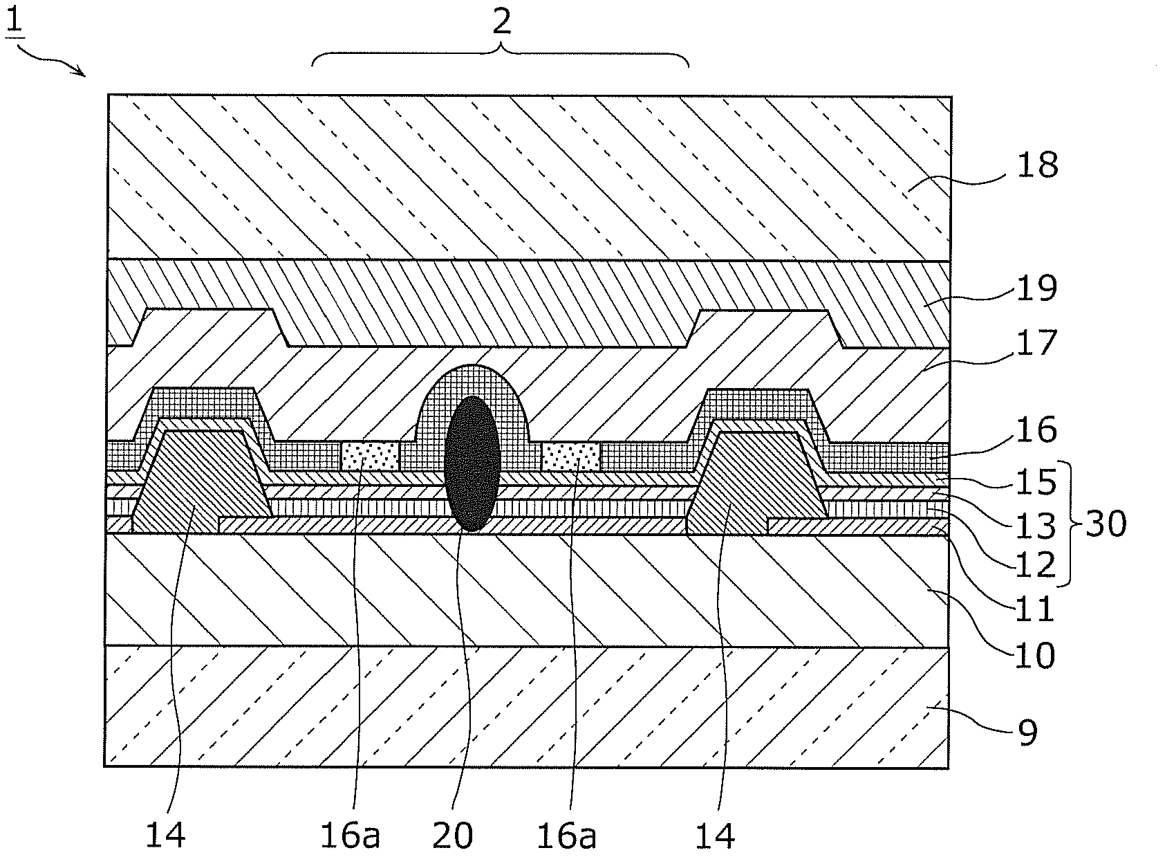
[0066] figure 1 It is a schematic cross-sectional view of the organic EL element 1 according to Embodiment 1 of the present invention. figure 1 The organic EL element 1 shown in is an organic functional device having an anode, a cathode, and an organic layer including a light-emitting layer sandwiched between the anode and the cathode.

[0067] Such as figure 1 As shown, in the organic EL element 1, a planarizing film 10, an anode 11, a hole injection layer 12, a light emitting layer 13, a partition wall 14, an electron injection layer 15, a cathode 16, a thin film sealing layer 17, The resin layer 19 and the transparent glass 18 are used for sealing.

[0068] The anode 11 and the cathode 16 correspond to the lower electrode layer and the upper electrode layer in the present invention, respectively. In addition, the hole injection layer 12, the light emitting layer 13, and the electron injection layer 15 correspond to the organic layer in this invention.

[0069...


PUM


Abstract

A method of manufacturing an organic electroluminescence device includes: preparing an organic EL device in which an anode, an organic layer including a luminescent layer, and a cathode formed of a transparent material are stacked in order and which has a shorted defective portion; irradiating the organic EL device with a laser beam from a direction of the cathode; measuring an intensity of radiated light from the organic EL device after the laser beam is absorbed through multiphoton absorption; changing a focal position of the laser beam in a stacking direction for performing the irradiating and measuring, and subsequently determining the focal position of the laser beam in the stacking direction such that the intensity of the radiated light is minimal; and irradiating the determined focal position with the laser beam, so as to solve a defect caused by the shorted defective portion.

Description

technical field [0001] The invention relates to a manufacturing method of an organic electroluminescent element and a laser focus position setting method. Background technique [0002] Conventionally, in an organic electroluminescence (hereinafter referred to as "organic EL") element with an organic layer interposed between an anode and a cathode, conductive foreign matter etc. may adhere or be mixed in the manufacturing process to short-circuit the anode and cathode. In this case, there is a method of repairing (removing) the short-circuited portion by irradiating the short-circuited portion with laser light (for example, refer to Patent Documents 1 to 4). [0003] In Patent Document 1, a conductive foreign matter adhering to an organic EL element is detected, and a laser beam is irradiated to an organic layer in a region around the foreign matter. This insulates the organic layer between the anode and cathode of the organic EL element to which the foreign matter adheres, ...

Claims


Application Information

Patent Timeline
Patent Type & Authority Applications(China)
IPC IPC(8): H05B33/10H01L51/50
CPCH01L2251/568H01L51/56H10K71/861H10K71/00H10K50/11H10K50/00
Inventor 平冈知己濑川泰生
Owner JAPAN DISPLAY DESIGN & DEV CONTRACT CO LTD
Why Eureka
Try Eureka